This avalanche pulse generator is a great way to test your mettle as an Electronics Engineer. The challenge is to truly understand how each part of the design works. We certainly got a failing grade when first studying the schematics more than a week ago. But we’re slowly beginning to understand what’s going on under the hood.
The concept of an avalanche transistor is some wicked voodoo from the analog side of the street which leverages a transistor’s breakdown voltage to achieve a predictable result. In laymen’s terms it (mis)uses a transistor to produce a really fast pulse. The write-up linked above references several previous avalanche pulse generator designs, but this one is a bit different in how it produces about 50V from a pair of AAA batteries using a multivibrator circuit.
Even if you have no idea what’s going on here you may be interested in the last few paragraphs where the circuit is measured using a cutting-edge Teledyne LeCroy Wavemaster 820Zi-A. That’s a 20 GHz scope with a 15.3″ screen which you’ll never ever own.


747ps rise time? That’s Cute.
150ps Pulse duration:
https://engineeringarts.files.wordpress.com/2012/07/pulse-metelics-5v.png
https://engineeringarts.files.wordpress.com/2012/07/signallaufplan.jpg
Thats a great pulse, can you provide more details on the circuit?
reminds me of the neon flashers from the dawn of history
you mean a Pearson–Anson electronic relaxation oscillator ?
and talking of old techs- I wonder what the fall time of a programmable unijunction transistor would be? On the ancient 20MHz CRT scope I picked up for a £5
waveform looks nigh on identical to the Jim Williams avalanche pulse generator
A 40GS/s scope claiming 20GHz reminds me of forty dollar ebay DSOs with 1MS/s claiming 1MHz bandwidth. It’s a 4GHz scope with a complex.
Nope. Keyword is equivalent-time capture.
Yeah with ETC, 20GS/s can get atleast 20ghz with no problem … 10ghz is probably a limitation in software!
But you forget that your samples make no sense above the nyquist frequency because of aliasing problems, so your actual bandwidth is a bit below half of your sampling rate.
That’s not true: the samples still make perfect sense above Nyquist. They just get aliased back into the lower frequency band. So what? If you’re only looking at signals from Nyquist to 2*Nyquist, who cares? You just filter out DC to Nyquist, and 2*Nyquist on up, and you’re fine.
You *have* to specify analog bandwidth and sampling speed separately. They’re two totally different things. The sampling speed tells you how much bandwidth you can measure (via Nyquist). The analog bandwidth tells you how high you can put that bandwidth.
Go look at the datasheets for ADCs, and you’ll rapidly see that most of them have far *higher* analog bandwidth than sampling frequency (which you never see in an oscilloscope), because many of them get used outside of the first Nyquist zone.
I have a 60MHz 20Ms/s scope in my closet, it can’t do 60MHz in single shot mode of course, but if you have a repetitive signal you can sample it several times while shifting the delay a little each time, building up a high resolution image of the waveform over several cycles.
Yes, I believe scopes using this basic concept were built with all valve technology by Hewlett Packard over 40 years ago. It was the only way to get GHz displays at that time
Why do you have to assume I will never own?
Kinda putting down your audience arent you.
Can I afford one, yep, do I have one? nope, but because I dont need or want one, I have several scopes.
Sensitive. I thought it was just a lighthearted joke.
oh, I recant.
a nice ;) at the end of the statement works well too ;)
I realized you recanted, but you realize this scope retails for about $164,000 right? (Plus calibration costs). I doubt any one person has ever privately owned this scope or any scope at this level when they’re in their prime. 20 years from now? Maybe …
We rented a couple of 40GHz scopes back in the old company. We could
easily afford them, but we only need them for a few months for hunting
down a major bug. The signals we were dealing with was a few GHz with
rise time of few hundreds of pico seconds. That was outside what our
usual scope could handle.
It is a bit of pain to do high speed measurement as the differential
probes (disposable) leads have to be soldered down. They were a bit of
pain in the rear to work with. At those edge rates, you cannot be sloppy
about anything – stub lengths, length mismatches.
I just can’t see myself wanting to use one at my spare time let alone
owning one. There is no point of owning them unless it help you make
enough money to pay for itself. I wouldn’t want to pay for regular
calibrations, consumables, support and maintenance on top of the price
of the scope either.
An interesting design is the “jim williams pulse generator”, there is even a kit available by “free_electron” a member of the EEV-blog forums and the dutch circuitsonline forum.
i have deadbugged up something similar with a hand picked transistor and a 60v switching boost IC
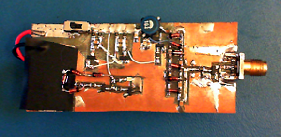
it REALLY should be deadbugged to prevent the bad capacitance and inductance this looks like it would have .. and shoved in a proper shielded case and have a BNC right on the end
Yea, i was thinking about that large copper plate not only being… well large, but also posing a risk of shorting and capacitance issues.
Probably better than doing it on a breadboard, though.
So what are the practical uses of such a circuit? I’ve come across three recently – and no one mentions what they’re actually going to be using them for.
My first thought was TDR (time domain reflectometry). A closed circuit radar to check transmission lines.
Detects changes in impedance and where (distance from the generator/oscilloscope). The faster the rise
time of the pulse, the greater the resolution in locating the impedance discontinuity. Handy to locate the bullet
hole in the coax to the antenna. Also to find taps on ethernet, etc.
Measuring the response time of an oscilloscope and deriving bandwidth. Filter design and testing. Glitch simulation.
I’m not a professional but these are the first to come in mind.
I used to make these to test circuits for counting pulses coming off PMTs
The scope is about 200k$ is this right?
EEVBLOG did a tear down of this scope and found it to be a Rigol 1052E with modified firmware ;-)