There are many different sensors that can be used to detect motion in a given environment. Passive InfraRed (PIR) sensors are the most used today, as they work by detecting moving heat signatures. However, they are less reliable in the hotter days and obviously only work for animals and humans.
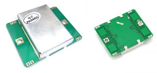
Sensors like the one shown in the above picture started to appear on the internet, they use the doppler effect to detect motion. I (limpkin) designed the electronics you need to add in order to get them to work.
Here is a simple explanation of the doppler effect: if you send an RF signal at a given frequency to a moving target, the reflected signal’s frequency will be shifted. It is commonly heard when a vehicle sounding a siren or horn approaches, passes, and recedes from an observer. The received frequency is higher (compared to the emitted frequency) during the approach, it is identical at the instant of passing by, and it is lower during the recession.
The Doppler motion sensor I bought only outputs a non-amplified signal of a few micro-volts, whose frequency represents the speed at which an object is moving towards or away from the sensor. The output can be very noisy, so in addition to amplifying the signal, I needed to filter out frequencies that don’t match what you can expect from ordinary objects.
I even made a simple video showing off the result:
[youtube=http://www.youtube.com/watch?v=q0HEF08JTtI&w=580]
All the files can be downloaded from my website, and I also made a fundraiser where I mention the predicted costs.


Neat stuff. Sort of off topic, anybody else feel a need to face palm at those people that try to scream something out the window as they drive by? These people do realize that the sound that reaches me is completely incomprehensible right?
I think the point, for them, is more in the shouting than in being heard. I bet you’re not missing out on much.
Apes do something similar. Til Daddy Ape gives them a slap down, then they shut up. Perhaps a lack of Daddy Ape is the problem here.
[youtube=http://www.youtube.com/watch?v=OX0EVN5hLgw&w=420&h=315]
Oh yeah..
well done!
ahahah… awesome!
This is the antenna/oscillator as used in the x band motion detector made by parallax:
http://www.parallax.com/Store/Sensors/ObjectDetection/tabid/176/ProductID/606/List/0/Default.aspx?SortField=ProductName,ProductName
If you just want a boxed version – they also have some more documentation.
It looks like this is for the HB100, while the Paralax model uses the GH100. The HB100 has a 20m range, while the GH100 is limited to 9m. Good catch, though. I wonder if they’re swappable.
I don’t really know what I am doing when choosing op-amps.
Can anyone tell me why the op-amp opa2365 was chosen for this, rather than the lm324 (or even a little cheaper perhaps a lm358) used in the application note?
lower input bias current, better CMRR
Dude. Awesome work man. I’ve been searching to an alternative to IR motion sensors for a long while now, and had thought about going with a laser tripwire system, but there are so many problems with changing light levels (sun comes out/goes behind clouds/it gets dark) and the sensor needs to calibrate to that environment to avoid false positives. This might just be the ticket to good detection every time. Thanks for sharing your work! it really helps!
Never designed one, but wouldn’t a good idea just be to modulate the laser? I remember reading plans for an IR “tripwire” using the same principle. Either simply modulate the laser to a frequency of a few KHz, then filter for that frequency at the detector, or possibly have wires between sender and receiver and use a more complex signal, checking the received signal matches what’s on the wire.
Either of these should be immune to noise. Also a good idea might be to use a little bit of black tubing, cardboard or whatever, attached to the Rx, so that it’ll need to be pointed directly at the Tx, but will block out all other sideways-oncoming light sources.
You could look into using the IR detectors they use for receiving TV remote controls. They automatically tune into and filter for a particular frequency, usually 38 – 44KHz. An IR laser modulated at 38KHz should do as well as the IR LED they expect. Their output is simply the demodulated signal. Perhaps experiment with a small lens or two to make the optics tolerant of small physical wobbles moving the laser beam.
Or forget the laser and just use IR LEDs, again, with tubing, should make the beam narrow enough.
Hey, great ideas, thanks for them. You know, I looked at that idea of modulating like most TV remote controls do, and it sounded feasible. The idea of “modulating” a light carrier isn’t what I would typically think of as “normal” modulation, at least in an analog sense, as one would do in radio, by speeding up and slowing down a wave (in the case of FM), or changing its amplitude (AM). With light, you’re having to literally turn it into on/off segments. PWM, I suppose, which IS modulation, just not what I think of typically. Do these remote control receiver modules just look for that pulse width, and when they find it output a signal?
Aiming of the device might be hard, in that one can’t see the laser. I’ve heard some cell phone cameras and handheld video cameras can see IR, so that might assist in the aiming process.
So, does anyone know where to find a cheap IR laser?
As an alternative to Greenaum’s idea, why not use a second sensor. Compare the levels at the laser receiver with an “ambient light sensor” nearby.
And the HB100 doppler radar Modules are pretty cheap. Only about $5
Its pretty much the same way police radar works. CW RF at microwave frequencies, in the US X, K and Ka bands, transmitted from a gunn diode/antenna horn/dielectric lens combo, said RF radiates your car, your car re-radiates that signal which returns to the police radar antenna horn at a new frequency due to the doppler shift, the radar head unit does the math wihich determines your speed which is then displayed to the officer. It’s also how many if not most automatic door openers on stores (CVS, Walgreens, etc) work except they only detect that there is a doppler shift, they don’t care about the delta of the frequency shift or your speed.
I guess what I was trying to say is, this isn’t anything new. If its cheaper than a stanely automatic door opener unit, yay! I guess… I wonder what frequency these work at? I’ll be angry if it’s X, K or Ka band… all RD users need are more RF drones…
And if you find a way to modulate the carrier with a slow (several 100s to 1000s Hz), you have a real FMCW radar ;-)
…with a slow *triangle* wave…
Incredible work using the doppler effect to create a motion sensor. It also seems like a really cost effective solution.
pir sensors detect motion, not people/animals. environment temperature has little effect. move a piece of room temperature paper across its field of vision, it will notice.
It detects differences in (heat) radiation…using only the background radiation for motion detection (no extra heat) will have very poor results…
Yup, that’s what the “IR” stands for. Interesting that Wikipedia seems to be having a slow edit war over this. But AIUI there are 2 thermal IR sensors in a bridge, one registering higher than the other creates an imbalance which is picked up by the circuit. The lens on the front focusses the IR, alternately across it’s width, onto each sensor, tho the lenses used can vary.
I fail to see how moving something room-temperature across it’s field of view would set it off, unless it detects the hand holding the bit of paper. It’s just a pair of thermal sensors, how would that work, Spyoxide?
If these use the same frequency ranges as police radar, then there goes my plan for a DIY automatic speed/distance adjusting vehicle cruise control.
I want one of those on my car so I can have cruise on and not be bothered by floppy footed drivers who can’t hold their speed within 5 MPH.
The range on these would have you tailgating the driver in front of you since it’s detection range isn’t all that far, being a low power, patch antenna device. Some “adaptive cruise control” systems use IR lasers, some use mm wave at around 75GHz which is well above the police radar bands. I’m guessing this is an X-band device which is a police radar band, but X-band is far and few between these days, unless it’s the Ohio State Patrol, they love X-band for some reason. The antennas for their radar are huge compared to K or Ka Band units. They sort of look like big spot lights mounted up on the driver side end of their light bars. with one facing forward and one facing aft. the reason they look like spot lights is they have an actual “lens” to help focus the RF beam, called a “dielectric lens”, made of a dielectric material like acrylic or TFE. If adaptive cruise control is messing with police radar or vice versa, or its setting radar detectors off, it’s more likely due to RF leakage from the cruse controls local oscillator or you just have a cheap cobra brand radar detector which will likely get you more tickets than save you from..
Any luck on your DIY adaptive cruise control project? I found these on ebay http://r.ebay.com/HW0Yh2 . Not sure of the range…
I used these for a university final project, the “DodgeBot.” 8 of these sensors around the perimeter of a plastic dome would sense oncoming projectiles (the dodgeball) and alert the MCU of the direction and speed of the incoming threat. The bots other sensors would detect a probable escape path and use mech wheels to get out of the way in whatever direction had the most room and wasn’t in the path of the ball.
I was responsible for the radars. Each unit had an NPN amplifier followed by an op-amp active filter (in order to ignore slow moving humans, the low frequency doppler shift) and then another op-amp that only passed signals past a voltage threshold (in order to ignore things that are too far away to care about). An arduino (for convenience – we did this in a month or so) monitored all of the signals and passed out status reports via the serial port to the MCU.
The main problem we had was that we took it to a large carpeted conference room to test the max speed of the unit and do some testing. The static electricity generated from the carpeting killed 6/8 of the radar units. I think probably because the battery negative wasn’t grounded to the chassis. It still worked alright when a ball was thrown at one of the two good radars. So beware – GHz frequency transistors are extremely static sensitive, these units will blow up easily.
i brought similar dopplar radar from china. at first sensor did not show any defects but after some days it became short circuited and i dont know how? what may be the cause of this. and also plz can someone send me the circuit of amplifier amplifies the sensor output.
Would the range of the detection be improved by the target having a corner reflector attached it? Can the sensitivity be effectively improved by narrowing the beam patterns (how can that be done?)
Presumably by determining speed and integrating then distance travelled can be determined?
Thanks for the help.
Steve
Kindly guide me is it HB 100 has its own library in arduino or not ?
Check this Micro-Doppler radar Module at Ancortek, website : http://www.ancortek.com . It can be applied to industry Automation, Medical Monitoring/Diagnosis, and Safety/Security: