We’ve never torn one apart ourselves, but it boggles the mind just a little bit to learn that these cooling fan controllers generate heat to do their job. We’d bet we’ll get shouted down in the comments, but doesn’t this seem counter-productive?
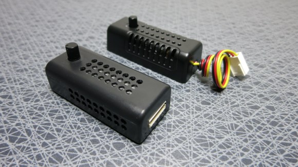
At any rate, we enjoyed reading two posts on this topic. [Göran’s] first adventure with the hardware started when he was trying to design his own speed controller. He saw a reference design in the LM7805 linear regulator datasheet which allows the adjustment of the output by changing the ground reference. When fed with 12V this ends up putting off some heat but it is a simple and reliable solution. He was a bit surprised to crack open a Zalman module and find the exact same circuit inside.
The controller in the background is an eBay purchase. He cracked that one open as well (that’s the link at the top) and found a circuit with a linear regulator in it, but this time it was a TL431 adjustable regulator. So here are our questions: Which one of these two is better and why. And can you do it relatively inexpensively without generating as much heat?


Oh wow, it’s funny to see how terrible some cheaply made devices are.
Cheap PWM regulators cause unwanted noise from the fan motors. Linear regulators are better in that respect, and the amount of power they dissapate is really insignificant anyways because computer fans aren’t exactly high power devices.
Given that contemporary fans with PWM control built right into the motor driver are easily available(it’s why they have four pins: power, ground, tach, and PWM), external voltage-regulator based speed controllers are really a lousy solution in search of a problem.
Do they allow you to run a bunch of the absolute cheapest two-wire fans you can find? Yeah. Are they even a remotely good approach when you can get cheap fans than control their own rotation speed in-motor? Hardly.
The issue is rather, that the fans you already have with your computer are of the two or three wire variety, and the properly made controllers to drive PWM fans are hard to come by and cost -a lot- more than a simple linear regulator, or even a simple 150 Ohm potentiometer that does the job perfectly well.
Most motherboards use Q-fan to drive the fans, so the PWM input pin is superfluous. The main advantage of PWM over voltage control is that helps the fan from stalling under low speed operation, but since Q-fan has feedback control it’s a more universal solution that comes cheaper both in terms of the controller and the actual fans.
Only difference between 3 wire and 4 wire is one transistor. And reason why is there is speed sensor. When fan is running on low voltage or PWM signal, output from speed sensor is useles. That is why they keep it on 12v and ad transistor for pwm. And also with this soulution you can use them on old 3pin motherboards. There is practicaly no difference in pwm control of 2pin, 3pin or 4pin fan.
Some of the larger fans can burn out the controllers on your motherboard and you don’t always have as many ports on your motherboard as you might like to have fans. Hence – fan controllers.
No no no. I must not be understanding something here, because I thought this was obvious of all such analog devices
Also, Dan you dummy, why don’t you try powering a remote LED during the off cycle instead of just heating?
They should only produce heat when they are slowing the fan down from its maximum voltage permitted speed. One would Slow the fan down when you have too much cool.. adding heat under these circumstances seems to be more efficient in that respect ;)
No. One slows down the fan when one doesn’t want to listen to a noisy fan. Or to make the fan last longer. I really doubt anyone is slowing their fans because their chips are getting to cold and they need to warm them up! Not unless they are operating their computers outdoors on Antarctica!
I’m not convinced that these controls put out enough heat to make this a problem worth solving but I disagree with the implication that adding heat is a good thing. Adding heat just means one has to turn the fan back up all that much sooner.
They do put out a significant amount of heat if you put strong enough fans on them.
When I was working at a computer store we had some fans die on the radiator in one of our liquid cooled display machines. Our solution was to put two high static pressure Scythe fans on in push/pull. Unfortunately the motherboard was out of fan hookups and the single cooling fan had previously been running at max all of the time direct from the PSU. We threw one of these cheapie fan speed controllers in with a Y connector to keep push and pull at the same speed and THIS happened: https://www.dropbox.com/s/28h2tgpmivo7x12/2012-11-14%2013.43.05.jpg
Here is a picture of one of the pull fans:
https://www.dropbox.com/s/rei13zb1c23fdy5/2012-11-14%2013.43.19.jpg
And if those fans had been plugged into the motherboard directly you would’ve burned out the port on the motherboard most likely. Been there, done that. My fans now all run full speed right off the PSU and yeah, I’d like a quality fan controller that could perhaps be computer controlled but I’m not willing to build one and I’m not going to spend a ton of money
Yeah but if you run those absurd things at full speed off of the PSU they sound like an airplane taking off. They’re 38mm thick and they run at 3000RPM (Scythe Ultra Kazes) I don’t even need that to running benchmark tests. The point is that they make almost no noise at all when they’re ramped down to the speed that you actually need.
I’m not kidding about the noise, you can hear those things three or four aisles away when they’re at full.
The way you (and others) set up those liquid cooling solutions is next to idiotic.
1) you /absolutely need/ a shroud between the radiator and the fan or your fan is just going to suck air through the gap, because the radiator has such high flow resistance. The shroud should cover the entire radiator grille and act as a funnel between the fan(s) and the radiator to get them to actually draw air through with a gap of at least 1″ between the fan and the radiator. The gap is there so the fan motor doesn’t “shadow” any part of the radiator, and to ease the airflow.
2) push-pull setup is bad for flow, because the fan exhaust flow is turbulent, so it has a hard time getting into the radiator. The closer the fans are to the radiator, the more the airflow has to turn to sink inside, or turn to meet the turning blades of an exhausting fan, and the more noise your fans make while moving less air. It’s not worth bothering with anything else than a pull setup.
3) The fans are bolted directly onto the metal radiators, which are bolted directly to the metal chassis, which conducts all the motor noise from the fans directly to the outside of the case, bypassing any and all noise dampening materials that might line up the case. You should instead use a rubber membrane with a hole for the fan to hang the fan to the shroud, or at least some soft rubber grommets between any hard parts.
By minding these three points, you can lower the noise levels and increase cooling efficiency dramatically. Do it the wrong way, and the liquid cooling typically underperforms regular air coolers that cost half as much.
Most kit sets make all three mistakes, because most manufacturers aren’t doing any sort of research on the subject. They’re just going by the seat of their pants, and/or copying what the other guys are doing, or they know that they’re doing it wrong but they also know that the customers don’t know any better so why bother?
1) The store at which I worked did not _stock_ fan shrouds. I’m aware of their utility and I have them on my own liquid cooled setup but I’m not going to spend personal money on a box that’s just supposed to sit there and look shiny to customers (and run folding@home).
2) I’d contest your assertion that push fans are useless. My old machine started with push-only and I saw a definite temperature drop adding one.
3) That top fan isn’t actually connected to the radiator, it’s just an exhaust fan. Look at the gap between the fan and the top of the case if you don’t believe me. The radiator is set to pull cool air in the back of the case and push it’s hot air out directly under that exhaust fan without effecting the rest of the case (much anyway), I just used the picture of that because it’s the same fan and it was the easiest to take a photo of at the time. Also, there is no sound muffling in the case, it’s a LANBOY air so it’s almost entirely open. There are however, rubber grommets and a rubber gasket employed on the screws holding the fans to the radiator.
*pull only
Both of these are going to put out heat to drop the voltage at their output. The TL431 will have lower efficiency as it is a shunt regulator where as the LM7805 is a series regulator.
If you want efficiency then use pulse width modulation. Perhaps a 555 timer with adjustable duty cycle driving a mosfet which switches the power to the fan.
Now that’s not right. Both will have the same efficiency save for a rounding error related to biasing the various components. In either case voltage is regulated by burning excess power as heat across a device. In the case of the LM7805 it’s the regulator and in TL431 it’s the transistor Q1.
Wasn’t there a solution to this posted here during the 555 design contest all that time ago?
I can;t find it. Oh well. Wouldn’t PWM however implemented be a better way to do it?
Sure! How about PWM generated by a 555?
Are you seriously paraphrasing OP’s original post as an answer to his question?
Are you seriously stating the obvious about a sarcastic comment?
A 555 controlling the pulse width to the gate of a FET in a buck converter is really all you need to create an adjustable DC-DC converter. Just make sure you dont leave the FET on too long and be careful of surge currents and you should be pretty much good to go. *Gross oversimplification*
Or even better, just use the FET to pass/block the current to the fan, no inductor needed
Right! You don’t need absolutely clean DC just to feed a fan.
That’s what a linear regulator does.
That was a mis-statement. Ignore me.
A search for “7805 replacement switching regulator” popped up several product. Here’s one of the crowd:
http://www.ttiinc.com/object/Murata-Power-High-Efficiency-Switching-Regulators-LM78xx-Pinouts.html
Any linear regulator solution will generate an identical amount of heat. The only solution is to PWM the power into the fan.
Additionally, many (probably most?) DC cooling fans on the market these days actually use *brushless* DC motors (rather than standard brushed DC motors). The brushless models have a control IC on board the fan (look under the fan hub for a round PCB), and many of those ICs will fail to work properly if given a raw square-wave output of a PWM switch. Some will burn up / smoke, others will turn at odd speeds, some won’t work at all, and yet others may have a variety of reactions depending on the PWM frequency. The most robust PWM solution will incorporate one or more low-pass filter stages on the output to the fan to guarantee compatibility with all DC fans, and maximize their lifetime.
To summarize, you need a SMPS :)
Exactly.
Of course, not all SMPS designs have ample filtering, and someone designing their own speed control might run into the problems I mentioned and bang their heads for hours (like I did) if they don’t realize that the AC component is the culprit. Many SMPS designs only have enough filtering to stabilize their feedback loop, and leave it to the user to put enough filtering on the output to achieve the level of stability that is needed.
I’m pretty sure all computer fans are brushless, but they can use really basic controllers. The minimum, which I think is pretty widely used, is a few Hall sensors each triggering a MOSFET to switch coils in the motor based on rotor position. A circuit like that shouldn’t mind being fed a square wave, so PWM on the 12v line ought to work.
The only fans which REQUIRE any sort of active logic are those with a 4-pin connector for a control wire (although other fans certainly might use it needlessly). In that case, you can still get away with PWM control, although you’d have to put it on the control wire instead of the power input. You’ll also have to make sure you match the specs for the control signal, which I think calls for 25 KHz.
If all it is just an adjustable power supply with the right fan
connectors, you can mod a dollar store cigarette lighter (12V) USB
charger by adding a pot. The switch mode ones should be able to handle
a few hundred mA and would be more efficient than a linear regulator.
I wouldn’t trust their rating, but the one I have tested is good for 300mA.
Sorry, no. As somebody above said, any linear regulator has to drop the same amount of voltage and thus generate the same heat. The only extra power an IC regulator takes (over your pot) is a few microamps for the internal voltage reference circuit.
On the subject of heat, if you reach 5V you should just use the computer’s 5v supply, no adjustment needed.
And then there are people that use the 5v and 12v lines to get 7V.as seen here http://www.silentpcreview.com/article6-page1.html
That’s how we used to do it back in the 90s. Brings back good memories of water cooled peltiers on Pentium 2 Slot CPUs. At the time, the only plans readily available on the Internet were this or an lm317 linear regulator. I personally used this setup for many years and it worked great.
Oops. I guess I didn’t read what you said. Disregard.
The reason you use an LM317 or other linear regulator for controlling fans is that it doesn’t impose switching noise on tach sense line like a switching regulator will. If you have noise all over your tach output, your motherboard (or circuit doing the reading) will display a false or unstable RPM value. And yes, actually very long ago I bought some of the Zalman controllers and opened one up and was surprised to see an LM317. And yeah, they dissapate heat in return for lowering the voltage, but allow your mobo to read the fan speed. I mounted mine outside of the case so the heat could go somewhere and so I could easliy adjust the speeds if needed.
Also, if you are dropping say 12 volts to 8 volts and it causes the 317 to dissapate X amount of power, the question would be can the fan efficiently remove that heat and the heat being generated by whatever you orginally intended to cool in the first place. Probably pretty likely vs. having no fan at all. Is it “green”? no…
If you have a larger computer case with more fans then the motherboard probably isn’t monitoring all of them anyway. You could feed the rest PWM.
On the flipside on a cheap dumb fan you have a far wider speed control if you PWM it than with a simple variable DC supply. The minimum turn speed becomes far lower.
I’ve used 555 doing pwm, works great.
3-Pin fans are regulated by changing voltage, so some adjustable switch mode regulator would do the job. If I’m not mistaken the venerable MC34063 could do the job rather cheaply.
Also Fan Speed “Tach” sensing to the motherboard won’t work if you apply a PWM waveform instead of a DC to the fan.
It is just an extra inductor + diode + cap away from a Buck Converter, not Rocket Science. Not sure why people like the 555 so much to not use a switch mode regulator chip like the MC34063.
A dollar store Car USB chargers that already have all the parts inside for a switch mode DC supply and all you need is a pot..
In other news the motors for cooling fans generate heat. Whatever will we do? How can these things possibly cool your computer if they generate heat!?!
I see what you did there :]
It’s almost as though some snake-oil of a fan salesman thinks we’re gullible enough to buy something that’s benefits outweigh it’s minuscule shortcomings.
You’re trying to tell me you want to sell me a window AC unit that makes heat on one side in return for cool on the other?! That’s counter-productive, I don’t care if the heat goes outside!
IMHO the issue isn’t with it raising the overall heat in the case, generally these controllers are left outside of the case anyway. The issue is with what happens if you ramp up the load on them https://www.dropbox.com/s/28h2tgpmivo7x12/2012-11-14%2013.43.05.jpg
simple use PWM 555 chip and effect transistor or mosfet
I created a temperature detecting speed controller a few years ago based around PWM, so it doesn’t generate the same heat a linear regulator would. Based around a pretty neat chip from Microchip. TC649.
http://widgetninja.wordpress.com/2009/09/25/pwm-fan-controller/
I just connect all my fans to 5V
if I find a fan that doesnt start at 5V I connect it between 5 and 12 rail = 7V
problem solved at NO COST
apart from when the PSU shuts down. Every time i’ve tried making 7v my PSUs have gone into short circuit shutdown.
Thats because the 5v rail is struggling to stay at 5v and the 12v is struggling to stay at 12v. I would recommend going the extra mile and just getting a regulator or DC-DC converter.
the 5v rail in the power supply is not designed to sink current, you need to have another load on the 5v to the ground that sink a little bit more current that the fan itself. That way, the load will sink the current returning from the fan and will take additionnal current from the PSU. Without this load, the 5v rail will sink current and cause the PSU to shutdown thinking its rails are shorted.
I use attiny’s for this. Took a while to get the RPM count working.I added a temperature sensor
and added bonus.. you can control it via buttons or with software directly from your pc that also reads out the values
or for the super simple pwm implementation : 1 mcu, 1 pot, 1 mosfet, 1 regulator, decoupling & bucket caps, a gate resistor, and you’re done…under 10 components, very little excess heat. good for dc fan or heating controller.
I’m surprised we haven’t seen premium PC fans with electronic speed control. Adjust the PWM control on the brushless motor -> increase or reduce speed without generating extra heat from a linear regulator. If the 3rd pin was used for 1wire or equiv. the speed could be under the control of the CPU.
We have seen them. Recent motherboards generally have new 4-pin fan connectors, they have seperate power and fan control (i.e. pwm) pins. Heatsink/fan combos coming with CPU boxes all have 4-pin fan connectors now.
Yes but even expensive motherboards mostly only have 2 or maybe 3 4pin connectors and any additional ones are 3pin. All of the sub-$200 mobos have only 1 4pin hookup for the CPU fan and the rest are 3pin.
Adjustable step-down buck regulators are cheap on eBay. There’s an energy loss with any voltage level converter but this is better than a simple linear regulator.
I’d recommend buying one of the cheap LM2596-based step-down converters on ebay. It will cost little more than 1 Euro per piece delivered directly from china. If needed, you can replace the build-in potentiometer by an external one.
Sample offer:
http://www.ebay.de/itm/Hot-DC-DC-Buck-Converter-Step-Down-Module-LM2596-Power-Supply-Output-1-23V-30V-/400552629658?pt=LH_DefaultDomain_2&hash=item5d42cc159a
A switchmode fan controller can be done as easily as this:
http://www.pcsilencioso.com/cpemma/555pwm.html
Although personally I’d drive the fans with a P-channel mosfet, since GND is also reference for the tach signal from the fan
I’d go with pwm and a cap.
I’d go with a Raspberry Pi/Arduino combo
I use a Tlc555 circuit (the same one from my ps3 fan controller) plus a transistor…very low heat, low noise, and low power draw. Plus it is safe for all fans and works with low current (cheap) pots. You can also do essentially the same thing with an attiny45…I just prefer a discreet circuit.
A linear regulator wastes (current x voltage drop) as heat.
Take the extreme example where the regulator doesn’t need to drop any volts. All of the power flowing is used by the load (the fan). At the other extreme, if the regulator is used to drop the fan voltage to 0V, then all of the current will be passed through the regulator.
The key insight here is that the total power (current x voltage) is the same in both cases. A linear regulator just diverts enough current to drop the voltage seen by the load.
So that heat it generates as a fan controller is the same heat that would have been generated by the fan motor itself if it was running at 100%.
1) most 12v and 24v BRUSHLESS fans i have EVER seen have a capacitor on the input
so no issues of square-wave altering it’s turning mechanism.
2) tach output problems with PWM ? use a level converter/buffer with low-pass filter on the buffer’s input. so the output is always 0v or 12v even if output is tach with pwm interference at lets say 8v
3) every last brushless 12v fan ive seen in the powersupply or cpu form-factor use less then 100ma !!! so power dissapation is a non-issue. i mean you can get away with no heatsink on linear speed controller, so it couldnt be THAT much heat.
4) those fans use LESS current when UNDERvolted!!! so your 100ma fan is now more like 75ma. even less to dissapate in linear transistor.
5) you add a fan why? because your CPU/GPU ect needs (extra) cooling of course!
and how much heat is it giving off? 50w? 100w? the extra heat from your linear speed controller pales in comparason.
with 5 fans at 100ma EACH that consume LESS with less voltage you get maybe (0.075a*5fans)*2.5v drop = 0.375a * 2.5v = juuust under ONE watt. nothing compared to your 3w soundcard or even a 15w cdrom(EDIT: 25w dvdrw), let alone a 100w CPU
pre moderating all comments over a certain size is encouraging trolls and discourageing real info.
real info is not 25 words or less. check the linked article, its more then 25 words right?
and if someone trolls using more then 25 words, chances are,
i will not be bothered by the extra stuff, i’ll skip over anyway
of course real info doesnt make ad dollars liek the trolling.
real info never refreshes the page waiting for an arguement
As I said in my longer post above, the heat can be enough to cause problems https://www.dropbox.com/s/28h2tgpmivo7x12/2012-11-14%2013.43.05.jpg
Most fan noise is cause by poor case design or too many ‘vents’. Some of these cases are like a frat house in summer; fans everywhere windows open next to a fan in the next window . No crossflow. Fans smaller than power supply size are whiners. Large and slow is the silent way. CPU fan should draw on outside air thru duct.
The easiest method is to use a resistor in series to limit the current, which will also lower the voltage. A 5W resistor that is more than enough for pc fans cost less than $1 and will barely get warm.
You can do all this other stuff but when dealing with something at such low power levels there really is no reason to over think it.
being a designer of speed controllers for fans, here my input:
First off yes you can use a 555 and it was part of the 555 contest, sadly the site is no longer up. You can use two 555’s one as the main osc and other in mono mode. First drives the second and you can control on time by voltage driving the control offset pin.
cheep fans can cope with basic voltage chopping but 99% of new ones die as they have a tiny micro in them for the commutation control. power cycling a circuit is never good for long periods of time. So yes a voltage regulator is way better. Some fans however don’t always start at the lower voltages so you need a controller that applies full voltage and then backs off – best practice anyway. regulators like 7805 are ok but yes make extra heat but trade off for being cheap. however a buck regulator or a smps will be much better!
Four wire fans if you can swop out are however the way to go as controls are dead easy then (PWM). new 4 wire fans don’t just have a extra transistor unless you but cheap stuff that your not expecting to last! they have micros and truly speed control inside the fan. There are lots of 25kHz fans but you will also find lots of PWM fans that will run down to 2kHz – nice for a little PIC project maybe?
If anyone has any questions please ask – happy to help! :o)
Paul ( aka @monpjc )
Ah! I knew there was! Thanks for confirming that I was not in fact imagining it! :)
PWM is a waste of time for small fans, simply use a resistor (100ohm)in series with the fan, with an electrolytic capacitor parallel to the resistor to provide a short full voltage pulse on power up (shunt) to get the fan spinning, then it will happily continue at the lower voltage with no PWM noise, only two components, win.
Very ignorant comment. You don’t limit fan speed with a resistor. Go to school or read books to learn why.
Think of it this way: 12V computer fan. 100 ohm resistor. How much current?
Your idea would be roughly appropriate for a motor alone by itself, but that is not what computer fans are. Take one apart to see what I mean.
Many fans are rated at 12V and 200mA. I know they’re active devices so we can’t really model them as resistors, but lets assume they’re steady state. Assuming that, they’d be about 60 ohms. Putting 100 ohms in series would net you 160 ohms, and a current of 75mA. The resistor would be dissipating 0.56W of heat. The fan would be seeing about 3/8th the current it would see before. I really don’t see what the issue is. There would be 7.5V dropped across the resistor and 4.5 dropped across the fan. That is pretty darn close to the 5V it would need to drive the logic in the fan. With the capacitor in parallel with the resistor, It would have plenty of voltage across the fan as it starts up. I fail to see the issue, I don’t see how this solution is any worse than using a linear regulator, except that it is not adjustable at all. I’d imagine his values won’t work in every case, but they certainly didn’t warrant a snarky comment “You don’t limit fan speed with a resistor. Go to school or read books to learn why.” Because in some cases yes, you do.
This just in: Cheap stupid shite you buy to tart up your PC is made cheaply and stupidly because people are cheap and stupid.
Ummm… why don’t you just wire up two fans in series, and then you will get the required voltage drop and no wasted energy being converted to heat. Each fan will then run at 6V instead of 12V.
I made a smart fan that monitors the final of a transmitter by using a small lamp in parallel with the high power collector supply resistor, then a phototransistor looks at the bulb, which applies current to a small power transistor in series with the fan.
(rain increases antenna load and tends to make the final overheat, this compensates for it, and if it’s cold enough the fan doesn’t run at all)
For computers, to reduce noise, I use bigger fans than needed and tie them to 5 Volts insted of 12, or use a 24 Volt fan on 12.
They run slowly and nearly silently..
Hello! Thank you for this post I am wondered if it is possible to use the same project for power supply. I guess it can be very efefctive way. For instance, i have this power supply http://hardware.nl/power-supply/dell/dx385.html and I will be very happy if it works in my case!