Programmable Zener Is Really An IC

[Kevin] doesn’t stock zener diodes anymore. Why? Because for everything he used to use zeners, he now uses TL431 bandgap voltage references. These look like zener diodes but have an extra terminal. That extra terminal allows you to set the threshold to any value you want (within specifications, of course). Have a look at the video below for an introduction to these devices and a practical circuit on a breadboard.

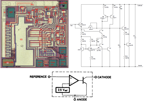
Inside, there’s a voltage reference, an op-amp, and a transistor, so these are tiny 3-terminal ICs. The chip powers itself from the load, so there are no separate power supply pins.

Continue reading “Programmable Zener Is Really An IC”

Ode To The TL431, And A LiFePO4 Battery Charger

Nerd Ralph loves cheap and dirty hacks, and for that we applaud him. His latest endeavor is a LiFePO4 battery charger that he made out of parts he had on hand for under $0.50 US. (Although we think he really made it for the fun of making it.)

The circuit is centered around a TL431 programmable shunt regulator, which is an awesome and underrated chip in its own right. If you don’t know the TL431 (aka LM431), you owe it to yourself to fetch the datasheet and pick up a couple with your next electronics part order. In fact, it’s such a great chip, we can’t resist telling you about it for a minute.

Continue reading “Ode To The TL431, And A LiFePO4 Battery Charger”

[Ken Shirriff] Explains The TL431

[Ken Shirriff] had to get down into a bit of semiconductor physics to give us an explanation of the TL431, which he calls “the most common chip you’ve never heard of”. [Ken] may well be right about the TL431. Even Texas Instruments can’t nail down a single name for it. Their page for the part calls it a “Adjustable Precision Shunt Regulator”, yet the datasheet is titled “Precision Programmable Reference”. You’d think they’d have figured this out by now, considering the TL431 was launched in 1978.

TL431’s can most often be found hiding in switching power supplies. The Apple II switcher had one, and many current ATX supplies have 3. Uninformed parts scroungers may miss them, as they often hide in TO-92 or SOT-23 packages. The TL431 is no transistor though. The TL431’s operation is actually pretty simple. When the voltage at the reference pin is above 2.5V, the output transistor conducts. When the reference voltage falls below 2.5V, the device stops conducting. In a power supply, this operation would help the control electronics maintain a stable output voltage.

The real subject of [Ken’s] article is the layout of the TL431 on its silicon die.  Rather than bust out the fuming nitric acid himself, [Ken] uses some of [Zeptobars’] decapped chip images. Inside the TL431, [Ken] discovers that transistors aren’t made up of the three layer NPN or PNP sandwich we’ve come to know and love. In fact, the base isn’t even in the middle. Transistors, including the BJT’s used in the TL431, can be assembled in a nearly infinite number of ways.

[Ken] moves on to the resistors and capacitors of the TL431. The capacitors are formed two different ways, one as a reverse biased diode, and the other as a more traditional plate style capacitor. The resistors include fuses which can be blown to slightly increase the resistance values.

The takeaway from all this is that once you get down to the silicon level, it’s a whole new ball game. Chip layout may look a bit like PCB layout, but the rules are completely different. [Ken] mentions that in a future blog he’ll go into further detail on the operation of the TL431’s bandgap voltage reference. We’ll be watching for that one, [Ken]!

Cooling Fan Speed Controllers Do It By Generating Heat

cooling-fan-speed-controllers

We’ve never torn one apart ourselves, but it boggles the mind just a little bit to learn that these cooling fan controllers generate heat to do their job. We’d bet we’ll get shouted down in the comments, but doesn’t this seem counter-productive?

At any rate, we enjoyed reading two posts on this topic. [Göran’s] first adventure with the hardware started when he was trying to design his own speed controller. He saw a reference design in the LM7805 linear regulator datasheet which allows the adjustment of the output by changing the ground reference. When fed with 12V this ends up putting off some heat but it is a simple and reliable solution. He was a bit surprised to crack open a Zalman module and find the exact same circuit inside.

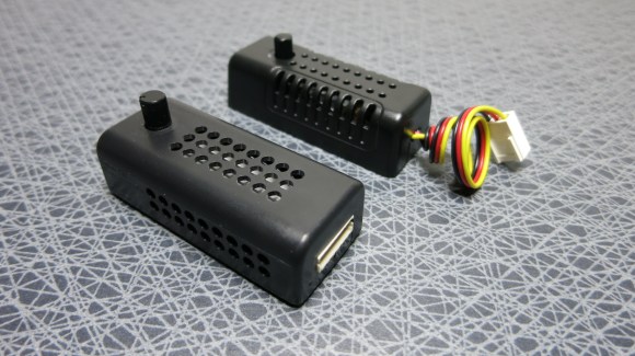
The controller in the background is an eBay purchase. He cracked that one open as well (that’s the link at the top) and found a circuit with a linear regulator in it, but this time it was a TL431 adjustable regulator. So here are our questions: Which one of these two is better and why. And can you do it relatively inexpensively without generating as much heat?