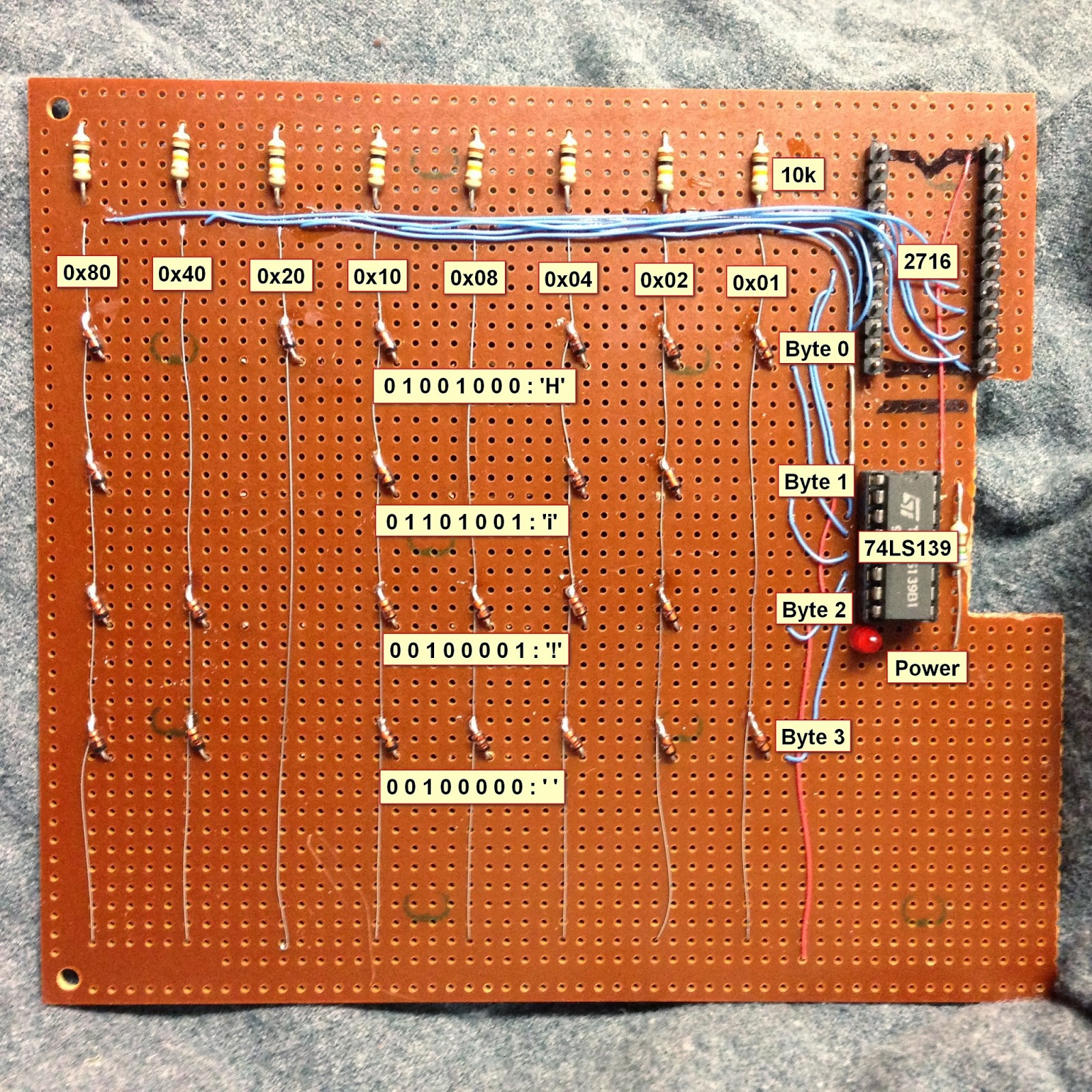
Here is a nice project that allows youngsters (but also adults!) to actually see the data stored in a Read Only Memory (ROM). The memory shown in the picture above is made of diodes. [Scott] made it as a part of his Barcamp Fall 2013 presentation about visualizing ROMs. He starts his write-up by stating the obvious: this memory is not practical. Nonetheless, it still was a fun exercise to do. [Scott] then greatly described all the different kinds of read only memories that you can find out there, with a few words explaining how they work. In his diode ROM, bits are ‘programmed’ by adding (or not) a diode between a given data line (anode) and an address line (cathode). When pulling low a given address line, the corresponding data line will only be pulled low if a diode is present. [Scott] finally checked his circuit by using a very old device programmer which could only be run in DOS.


He doesn’t mention that these types of diode arrays were actually used in some of the very old mainframes from the 60s and earlier, mostly for microcode. I only mention this because the lack of discussing it makes it sound like this was a pie-in-the-sky idea that popped up out of nowhere. “Practical” is relative, compared to today’s technology, but “practical” given that these types of arrays were actually used in production.I know i”m being pedantic.
I did make a mention of their use in the beginning paragraphs, but I’ve made it more specific by mentioning the PDP-11. Thanks!
Pedant away my good man! These kids today do not respect memory. It still matters!
Could be practical using a SMD and pick and place for small ROM’s
I actually made something like this to supply a JMP instruction to force execution of EPROM code at a high memory address on reset, in an 8080 based system.
Clever!
Your comment makes me want to write a very small Z80 program and compile it to diodes, and run it. heh
Diode based ROM can actually be a practical solution for mapping a small set of inputs to a small set of outputs, like in this telepresence robot…
http://josh.com/notes/bitlybot/
You can also use LEDs as the diodes (LEDs really ARE diodes!) and it makes it very easy to see what is going on in the circuit in real time.
… and wasn’t it Bill Gates that said “nobody will ever need more than 4 bytes of ROM anyway”.
It would be even cooler if he used LEDs for it
Now that is a brilliant idea + 1
I contemplated doing this, but being the current usage of the LEDs would be different than diodes, I wasn’t sure how it would work out. Also, it is read VERY quickly, so they’d basically appear to be always-on…. Although that would emphasize their “one-ness” or “zero-ness” quite nicely. I’ll explore this more…
I like your zero ness to one ness, like ying and yang, imagine a t shirt, YOUR ONENESS WILL ALWAYS SHINE THROUGH D2, gives me goozies thinkin bout it.
The VOL of this “ROM” already violates the TTL specs of VIL of 0.8V(Max).
Forward drop 0.6V + 74LS139 VOL 0.3V = 0.9V
If the silicon diode were to be replaced with LED, all the outputs would
be stuck at logic ‘1’. Red LED has lowest forward drop of 1.63V + 0.3V =
1.93V which is pretty darn close to VIH = 2V (min)
Beside you are driving the LED at (5V-0.3V-1.63V)/10K = 0.3mA and
coupled with very narrow pulse width for memory cycle in hundred of
nanoseconds, you are not going to see it.
Density can be improved a lot, though. Start with perfboard with line pattern, and stick the diodes in vertically. Don’t skip holes. Snip off excess leads on the top, and solder them to a wire. You could even bend one of the leads and use that as the wire.
You would still struggle to get more than about 1/2 kB on the perfboard though. Enough for a small monitor program or bootloader perhaps.
All of about 32 bytes is way more than enough to make a bootstrapper. Caveat: Depends heavily on the instruction set and hardware.
One of the simplest ways is to use a parallel port with a clock line, reset, and single word input. A serial port is about the same if the hardware does the flow control and DMA. Once the interface fills the program memory, just jump to the beginning of your code. And of course, you can repeat this in an onion-style setup for more complex programs with more efficient (say, Ethernet) ways to transfer large amounts of data.
Once you can get it to boot, you can hook up a 27xxx chip and burn it through the same board that it’ll be booting next time. Presumably, most people who’ve done this used the same pinout as a parallel-interface EPROM without as many address pins. ;) The hot swapping isn’t even an issue if you use a MUX board (high address line goes to #CSx/CSx lines). Many memory devices have CS0-2 (3 inputs, 1 opposite logic-polarity of others).
A neat trick once you get it to bootstrap to an IC ROM, is to make the bootstrapping code check to see (say a switch on the board or some checksum) if the EPROM has already been written, and stop trying to update it. This doesn’t have to be the same as the diode-ROM code, obviously. You can make a more convenient upgrade/burn routine which takes up more space.
Did a bit of Googling and found these:
http://forum.6502.org/viewtopic.php?t=1526
http://forum.6502.org/viewtopic.php?f=12&t=2710
Enjoy!
If you’re going to try to make it work with 4 bytes of ROM, you might be better off using one of the ROM-less solutions. You literally just pause the PC and fill a buffer. You feed it the opcodes and data bytes to write to RAM. This is super cheap but only works on CPU’s that can run statically (<1KHz).
Yes, it can be massively condensed to be MUCH smaller. There were a few factors involved with this though…
Being that I was hand-wiring it, it would have taken substantially longer. I also had a limited number of diodes in my parts bin. As it is, I reduced the content from “Barcamp!” to “Hi! “, to use fewer diodes and fewer address lines. I would have also had to figure out a more complex address decoding, as the ‘139 has two sets of 2 bits in. I could just use an extra inverter and some ORs to achieve this though…. Or a logic interface based on diode logic as well… ;)
Wish I could edit replies…
http://www.jdm.homepage.dk/z80boot.htm For the Z80. I’d seen this before but had to do some looking to find the link. 2 chips to boot is pretty nice, eh? :)
There used to be a company that sold a grid socket that was perfect for this as you could bend the diodes and just plug them in allowing for a “poor mans” prom. 16X16 grid on .1 spacing that could be stuffed next to each other tightly.
More, more! :)
Perhaps you could make it programmable like a PROM (once) by burning the diodes with the application of a high current from the programmer.
I love the smell of burning diodes in the morning..,
When you “burn” a diode, the high current heats up the junction and turn it into a short (most of the time).
After which, even more current will blow it off of the board!
I used something like this to throw a number of switches in a model railroad yard. You determine the track (address) and the diodes determine which switches to throw to get your train on that track.
The diode matrix is a good learning tool, but in practice it suffers from a lack of speed due to the slow diode-resistor transitions. It also take a lot of real estate and is a nightmare to wire together.
A much more efficiient solution in terms of speed, size and wiring difficulty is using only 4x dual 4-bit 74153 multiplexers with inputs set to the bit value and select inputs used as word select:
http://imageshack.us/a/img22/5495/swnw.png
All Transistor-Transitor Logic (TTL), easy to reconfigure with only jumper wires, no programming device required for an easy low-density memory!
You could also add a precharge circuit to speed up the ROM. Use a mosfet in parallel to the pull-up resistor, and quickly pull it back up to high level during inactive phase of the clock.
I saw a morse terminal project in a late 60’s, early 70’s electronics magazine that used a diode ROM to decode a keyboard matrix into morse
This brought back memories. I worked with PDP-11s back in the 1970s. The diode ROMs had the boot code in them. You programmed the memory by removing diodes from the array. A brief search turned up this: http://www.cca.org/blog/20120222-Diode-Matrix.shtml
I’ve got an old 2M mobile ham radio that used a diode matrix to program frequencies in. It was one of the first synthesized radios, iirc. ICOM IC-22S.
Let’s see… If you had a 2×14 DIP header (in practice, 14-pin SIP headers), a 28-pin DIP socket, the diode ROM logic(address+array), and what ever is needed to program the EPROM, then you could use that. I still say to use a buffer chip and parallel port. If you wanted to ‘cheat’, BASIC stamps can program a Flash ROM through their port? ;)
If your dreams face to the lack of components this leads to a diode ROM of 63 bytes of code for starting 5 functions: Write, Read written code(forward and back), chose memory segment of 256 bytes and Run the code. It is enough to start creating for 8051 some monitor codes.