Homebrew Programming With Diodes

diode

Diode matrices were one of the first methods of implementing some sort of read only memory for the very first electronic computers, and even today they can be found buried deep in the IPs of ASICs and other devices that need some form of write-once memory. For the longest time, [Rick] has wanted to build a ROM out of a few hundred diodes, and he’s finally accomplished his goal. Even better, his diode matrix circuit is actually functional: it’s a 64-byte ROM for an Atari 2600 containing an extremely simple demo program.

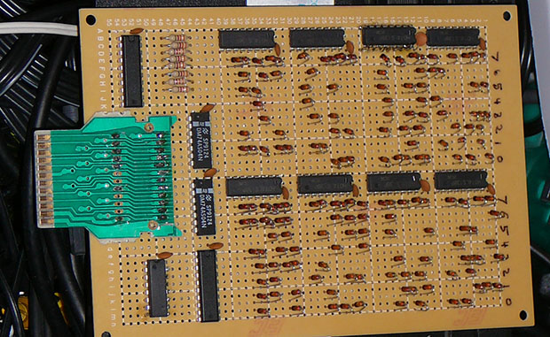
[Rick] connected a ton of 1N60 diodes along a grid, corresponding to the data and address lines to the 2600’s CPU. At each intersection, the data lines were either unconnected, or tied together with a diode. Pulling an address line high or low ([Rick] hasn’t posted a schematic) pulls the data line to the same voltage if a diode is connected. Repeat this eight times for each byte, and you have possibly the most primitive form of read only memory.

As for the demo [Rick] coded up with diodes? It displays a rainbow of colors with a black rectangle that can be moved across the screen with the joystick. Video below.

Continue reading “Homebrew Programming With Diodes”

ASAP 3 – The Almost Simple As Possible Computer

ASAP-3 12 - LED Display

[Pong] has joined an elite club of people who have designed and built their own computer – including a CPU created from discrete 7400 series logic. His computer is the  Almost Simple As Possible Computer 3 (ASAP-3). ASAP-3 is not a completely new design. The architecture is based upon the SAP series of computers from Albert Malvino’s book, Digital Computer Electronics. [Pong] looked at quite a few of the “modern retro” computers such as Magic-1Big Mess o’ Wires 1, and the Duo. These computers were beyond his skill levels back then, so he began to build his own system. His primary design goal was to be able to run a 4 function calculator program.

One thing that can’t be stressed enough is the fact that [Pong] made his design work much easier by using lots of simulation. His tool of choice was Proteus Design Suite. While simulation can’t solve every problem, it can often help in verifying that a given design is sound. The ASAP-3’s instruction set is microcode, based upon the 8085 series instruction set. The microcode itself is stored on Flash ROMS. Using microcode makes ASAP-3 very flexible. Don’t have a machine instruction you need? No problem – just write one up. When all was said and done, [Pong] had over 100 instructions spread over 3 Flash ROM chips.

The hardware was only half the battle – [Pong] found writing the software just as challenging. He wrote all the software by hand in his own machine code. This is where the simulation mentioned above really saved him some time. Even with simulation he still ran into some problems. The ASAP-1 is limited to a clock speed of around 500kHz. Above that, glitches from the ROM chips start triggering the asynchronous inputs in some of the registers. [Pong] doesn’t have a logic analyzer on hand, so he wasn’t able to track this one down further. He also found a (update simulation only) issue with the carry bit on the 74LS181 bit slice ALU. In certain circumstances the carry bit would not propagate correctly. [Pong] corrected this by using a ROM as a look up table replacement for certain ‘181 functions. Even with these limitations, this is still a great hack!

Continue reading “ASAP 3 – The Almost Simple As Possible Computer”

Making A Diode Matrix ROM

Here is a nice project that allows youngsters (but also adults!) to actually see the data stored in a Read Only Memory (ROM). The memory shown in the picture above is made of diodes. [Scott] made it as a part of his Barcamp Fall 2013 presentation about visualizing ROMs. He starts his write-up by stating the obvious: this memory is not practical. Nonetheless, it still was a fun exercise to do. [Scott] then greatly described all the different kinds of read only memories that you can find out there, with a few words explaining how they work. In his diode ROM, bits are ‘programmed’ by adding (or not) a diode between a given data line (anode) and an address line (cathode). When pulling low a given address line, the corresponding data line will only be pulled low if a diode is present. [Scott] finally checked his circuit by using a very old device programmer which could only be run in DOS.