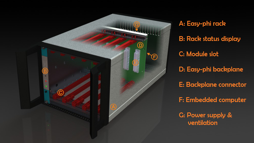
As a few of Hackaday readers may already know, my day job involves working with high speed electronics. For the last few months, my team at [Université de Genève] in Switzerland has been working on an open source platform (mostly) targeted for experimenters: the easy-phi project. The main idea is to build a simple, cheap but intelligent open hardware/software platform consisting of a 19″ frame (or smaller), which can house a big variety of electronic modules. Hobbyist would therefore only make/buy the modules that would suit their needs and control them through a web page / standalone application / Labview module.
I detailed in more depth on my website the technical aspects of the project. To give you a quick and simple overview, the rack is essentially a USB hub that connects all the modules to a Cubieboard. It also integrates a few synchronization signals, a clock and a monitoring system for voltages, temperatures, power consumption. The modules are made of template + module specific electronics. The template electronics are part of the ‘easy-phi standard’, they consist of the Arduino compatible SAM3X8E microcontroller and of a few other power related components. This ensures electrical and firmware compatibility between the rack and modules that you guys may develop. It is important to note that the modules are enumerated on the USB bus as composite CDC (communication device) and MSC (mass storage). The CDC is used to configure the module while the MSC allows you to grab its documentation, resources, and standalone application in case you use the module without the rack.
The chosen schematics / layout software is Kicad, and all current files can be found on our github. Others will be uploaded once we have tested the other modules currently in the pipe. As the ones we’re developing are physics oriented, we hope that enthusiasts will bring easy-phi to other domains. Don’t hesitate to contact us if you have any question or if you’d like to contribute.


Eurocard revival ? :D
ahaha yes :), only way to have a cheap rack!
“I detailed in more depth on my website”
Ummm, why USB 2.0?
Wouldn’t 1Gb ethernet be way better suited for this application?
USB 2.0 is for module backplane communication. It is not meant for heavy data transfer (just the few files & ressources). Moreover USB was much easier to implement than ETH.
IMO lack of a realtime communications protocol is going to leave something to be desired. There’s a lot you can still do with USB, but frame rates are a @#$!@%
We actually thought of that. Modules that require realtime communications will do so via their front panels.
It’s a pain in the ass to find non NDAed Gb ethernet switch….
Why don’t just use MTCA.4?
too expensive for us…
Indeed. I reckon you can run out of bandwidth real quick using USB2.0 as the backplane…
If you’re going to make a backplane why not go with the S-100?
from what I can find on it, we wouldn’t be able to pass a 480MBits/s USB 2.0 on it.
Looks like the NI PXI platform… looks promising though
Er, what’s happened to the HaD layout?
It doesn’t look right.
Glad to see I’m not the only one…
Failed to load resource: the server responded with a status of 404 (Not Found) http://s0.wp.com/wp-content/themes/premium/genesis-v1/style.css
It kind of reminds me of the Altaire, just way more powerful
You Could also look at Ross Video’s OpenGear Series
http://www.rossvideo.com/terminal-equipment/opengear/
Seems like a solution looking for a problem, and most likely out of budget for anyone without a corporate budget or academic grant. The only thing it has going for it is being open source, but since it doesnt require 3rd party modules to be open source, it kind of defeats the point. Somehow I dont see this being particularly successful.
We’re developing it because of the actual demand coming from the university. I’ll grant you that it’ll be a bit expensive but we’re doing everything we can to lower the costs.
I welcome a cheap, open source alternative to NI’s or other (incredibly expensive) card-based systems. An easy-phi chassis with a couple of cards from the list of planned modules could add extraordinary flexibility to any maker’s workbench.
Still, I think you are crippling your platform by having a backplane that only supports USB 2.0. Adding 1GbE through the backplane connectors in parallel to the USB 2.0 would make this a far more attractive solution in my mind. It need not be supported by every module, but as long as the option is available for higher data rate, reasonably low-latency communication between cards this could be very useful.
All you really need to to is to reserve the pins and carefully route 4
diff pairs from each of the connectors in the backplane to a fabric/CPU
slot. When/if Ethernet is needed, upgrade the card to one that have
Ethernet fabric.
USB 2.0 as a hotswap/management/low bandwidth control interface is an
interesting idea. It is much better than a bussed I2C that I am used to
see on a backplane. I am however not particular crazy about mandating
the CDC and MSC. I would have choosen the Cypress CY68xxx FX2 chip as
they have a FIFO interface that can easily move data at 30-40MB/s.
(answer from a colleague)
For us it is very important that the system is not too expensive and lasts for quite a while. Connectors that carry GHz signals are more expensive and to avoid reflections due to stubs , it is probably necessary to have the routing of these signals on the backplane as point to point connections. ACTA would work but it is very expensive. We prefer using a 10MHz clock (high accuracy) and four synchronization signals for simple tasks between modules.
For more acurate and/or faster communications between modules, it always is possible to put connectors on the front panels.The advantage is that if the data transfer technology evolves, we just need to adapt the module and not the rack.
You caution is unwarranted.
FYI Gigabit Ethernet is 4 pairs of full duplexsignals and only requires
about 80MHz worth of analog BW as they use PAM5 encoding and modify
their rise/fall time to minimize EMI. There is very little stubs in the
DIN connector construction you are using. See harting datasheet for the
cross-section diagram on what the pins/sockets looks like.
Small amount of impedance mismatch/inperfection can be tolerated. It is
not like the Ethernet connector is impedance controlled.
By the way if you are already routing 480Mbps USB 2.0 signals on the connector, you wouldn’t have to worry about 125M baud PAM5 signals!! LOL.
YES THANK YOU i have been wanting somthing like this for awhile! dont forget to make big ass perf boards! XP
that’s good to hear!
Looks like perhaps a 50-pin backplane connector, with all pins committed – mostly by parallel power connections. You sure you don’t want to leave at least a *few* uncommitted? For future Ethernet, a low-current -12V rail for op-amps, or whatever?
we want to keep the backplane as simple as possible. Power is provided through a 12V PSU and it is up to the modules to generate the voltages they need. Leaving pins uncommited makes room for future incompatibilities between modules
There is a US company that makes this….
http://2.bp.blogspot.com/-8LbhijvYPF8/UpPxKdXP_hI/AAAAAAAABCE/zfrJ9RzMwyk/s1600/DRT-2101.jpg
If each module had a VISA interface then what is the advantage of the backplane, other than shared power.