[Brian] had an absolute monster of a PCB with thousands of nets to be routed, the kind of design that stopped traditional routers in their tracks. It would take months to route by hand, likely trying the patience of a saint in the process. To solve this specific problem he created OrthoRoute, a GPU-accelerated autorouter that he cautions is no more trustworthy than any other autorouter, but at least it’s fast!
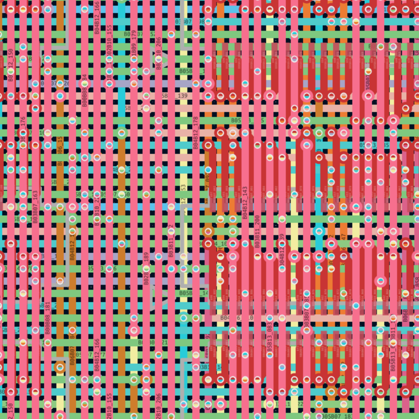
A KiCad plugin, OrthoRoute is so named because traces are laid down in a Manhattan lattice, a grid of orthogonal segments. All components (surface-mount only, no through-hole stuff) go on the top layer of the PCB, and all lower levels contain a grid of traces, connected as needed with blind and buried vias to route everything. OrthoRoute takes a structured and iterative approach, eventually converging on a satisfactory layout.
How does OrthoRouter actually decide how to connect things? [Brian] adapted PathFinder, an algorithm designed for routing FPGAs. Laying out a grid of orthogonal traces and punching down through them with vias to make connections has a lot in common, conceptually, with routing FPGAs. GPU acceleration makes the whole thing far more efficient than pipelining the calculations through a CPU.
OrthoRoute was built to solve a very specific problem, but in the process showed that GPU-accelerated routing is definitely feasible. Check it out in the videos, embedded below the page break.
[Brian] cautions that as-is, OrthoRoute is useful to maybe a handful of people at best, but as a KiCad plugin it’s highly modular and the hard parts are all done. If you want a closer look, or have some ideas about how to repurpose or extend it, check out the GitHub repository.
We’ve seen some nifty KiCad plugins for all kinds of purposes, from breadboarding to giving PCB traces an old-timey look, and even one specifically for designing custom keyboards. It’s not every day we see a plugin aimed at handling high-density boards with thousands of nets, though.
Continue reading “GPU-Accelerated Autorouter Handles Monstrous PCB Designs”