3D Printed Cutaway Jet Engine Sounds Great

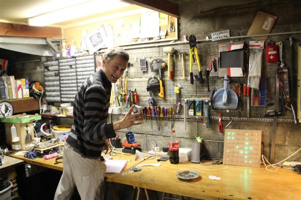
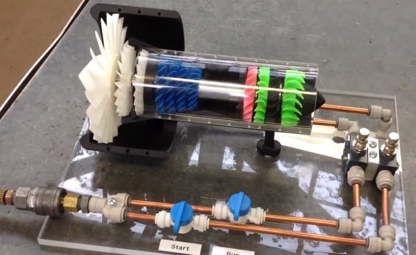
Thanks to the wonders of 3D printing, you can now have a 3D printed a jet engine of your very own. Unlike jet engines we’ve seen before, this one comes with no chance of the operator getting burned to a crisp. [Gerry] is a self-proclaimed “broken down motor mechanic” from New Zealand. He’s designed a rather awesome jet engine in 3D Software, and printed it on his UP Plus printer. The engine itself is a cutaway model of a high-bypass turbofan engine. While we’re not sure which make and model of jet engine this cutaway represents, we’re still very impressed.

This isn’t just a static display model – the engine will actually spin up with the help of compressed air.  Separate start and run tubes send air to the turbine and main fain respectively. It even has that distinctive turbofan “buzz saw” sound. While this model is relatively safe, [Gerry] does warn to keep the pressure down, or it could come apart. To that end we’d recommend adding a regulator before the quick disconnect.

The Thingiverse project is a bit light on instructions.  However this situation is remedied by [hacksaw], who posted a pictorial and build log up on pp3d. [Hacksaw] did run into a few problems with the build, but nothing a little bit of superglue couldn’t fix. It may have fewer moving parts, but this definitely puts our old Visible V8 Engine kit to shame.

Continue reading “3D Printed Cutaway Jet Engine Sounds Great”

Making An Airgap Flash

[Maurice] and his team just finished the airgap flash they’ve been working on for a year now. This kind of flash is useful for very high speed photography such as photographing shooting bullets. With a duration of about a millionth of a second it is 30 times faster the normal flashes at their fastest settings. In the video embedded after the break, [Maurice] first explains the differences between his flash and a conventional one which normally uses a xenon flash tube, then shows off different photos he made with his build.

Even though this video is a bit commercially oriented, [Maurice] will make another one detailing the insides. In the mean time, you can checkout the schematics in the user manual (PDF) and also have a look at an other write up he made which we covered in the past. We should also mention that trying to make this kind of flash in home is very dangerous as very high voltages are used (in this case, 16kV).

Continue reading “Making An Airgap Flash”

Hackerspacing In Europe: Open Garage In Antwerp

Welcome to Europe’s smallest(?) hackerspace, whose owner, [Anthony Liekens] might just have the biggest heart! This is the Open Garage!

You might remember the recent post about the 3Doodler in the wild. That was done by [Anthony] and his close friend [Deepak]. After we shared his project he contacted us by email, opening an invitation to visit the Open Garage — as it turned out, we were going to be in close proximity to it in Antwerp, Belgium! After visiting Void Warranties, [Anthony] invited us over for a beer and tour of his unique hackerspace…

Continue reading “Hackerspacing In Europe: Open Garage In Antwerp”

HeartBeat Boombox Creates Bio Beats

sophi1

If you happened to be wandering the hall of science during MakerFaire NY, you may have noticed a woman walking around with a rather odd boombox strapped around her neck. That was [Sophi Kravitz] with her HeartBeat Boombox. Thankfully [Sophi] lives within driving distance of Makerfaire, and didn’t attempt to get through airport security with her hardware. She started with three medical grade pulse oximeters. These oximeters output a “beep” for every beat of your heart. [Sophi] rolled her own AVR board running Arduino firmware to capture pulses on their way to the oximeter audio transducer. The AVR uses a sound board to convert the pulses into various percussion sounds. The pulse indicators also activate one of three LED strips.

[Sophi’s] biggest frustrations with the hack were the JST connectors on the LIPO batteries powering the entire system. She found that they fell apart rather easily. We’ve used JST connectors in the past with no problem, so we’re guessing she ended up with one of the many knock off connectors out there. [Sophi] tied the entire system together with a custom milled acrylic plate mounted to the front of the boombox.

The final result was very slick. With three people connected to the finger inputs of the pulse oximeters, some complex beats could be formed. We thought we were listening to dubstep when she first walked by. One feature we would like to see implemented would be the ability to record and play back some of the beats created by the boombox.

CAN Hacking: The In-vehicle Network

Last time, we discussed how in-vehicle networks work over CAN. Now we’ll look into the protocol and how it’s used in the automotive industry.

The Bus

On the hardware side, there’s two types of CAN: differential (or high-speed) and single wire. Differential uses two wires and can operate up to 1 Mbps. Single wire runs on a single wire, and at lower speeds, but is cheaper to implement. Differential is used in more critical applications, such as engine control, and single wire is used for less important things, such as HVAC and window control.

Many controllers can connect to the same bus in a multi-master configuration. All messages are broadcast to every controller on the bus.

An oversimplified in-vehicle network

Continue reading “CAN Hacking: The In-vehicle Network”

Retrotechtacular: Steam Locomotive Construction In The 1930’s

Here’s a fascinating look at high-tech manufacturing in the 1930’s. This week’s Retrotechtacular features the building of a steam-powered locomotive. The quality of the black and white footage, and the audio accompanying it are almost as impressive as the subject material — which is nothing short of a machinist’s wet-dream but also includes much forging and smithing. Digging through the video for a suitable still image was a tough task, as every step in the process was interesting to us. But this image showing some of the 2700 feet of tubing used in the locomotive seems most appropriate.

The build covers all aspects of the build. Huge sheets of steel make up two side plates between which the cast engine block is mounted. The mold for casting was huge, required twelve hours dry time before the pour, and took a day or two to cool before breaking the mold. That yielded a rough block which then headed off for machining.

We were delighted by the crane used to transport steel sheets from the oven to a stamping machine. The counterweight is workers (and lots of them) on the other side of the fulcrum. After a glimpse of the ancillary part fabrication you begin to get a look at the complexity of the machine as it is assembled.

Does anyone feel a deep appreciation for the pedagogy that went into making something like this? What we mean is that the teams building No. 6207 don’t seem to be using skills learned in a book or from a class, but rather those passed down from the masters that have been on the job most of their lives. Watching them all work is nothing short of astounding!

Continue reading “Retrotechtacular: Steam Locomotive Construction In The 1930’s”

Easy-phi: An Open Source Platform For Experimenters

As a few of Hackaday readers may already know, my day job involves working with high speed electronics. For the last few months, my team at [Université de Genève] in Switzerland has been working on an open source platform (mostly) targeted for experimenters: the easy-phi project. The main idea is to build a simple, cheap but intelligent open hardware/software platform consisting of a 19″ frame (or smaller), which can house a big variety of electronic modules. Hobbyist would therefore only make/buy the modules that would suit their needs and control them through a web page / standalone application / Labview module.

I detailed in more depth on my website the technical aspects of the project. To give you a quick and simple overview, the rack is essentially a USB hub that connects all the modules to a Cubieboard. It also integrates a few synchronization signals, a clock and a monitoring system for voltages, temperatures, power consumption. The modules are made of template + module specific electronics. The template electronics are part of the ‘easy-phi standard’, they consist of the Arduino compatible SAM3X8E microcontroller and of a few other power related components. This ensures electrical and firmware compatibility between the rack and modules that you guys may develop. It is important to note that the modules are enumerated on the USB bus as composite CDC (communication device) and MSC (mass storage). The CDC is used to configure the module while the MSC allows you to grab its documentation, resources, and standalone application in case you use the module without the rack.

The chosen schematics / layout software is Kicad, and all current files can be found on our github. Others will be uploaded once we have tested the other modules currently in the pipe. As the ones we’re developing are physics oriented, we hope that enthusiasts will bring easy-phi to other domains. Don’t hesitate to contact us if you have any question or if you’d like to contribute.