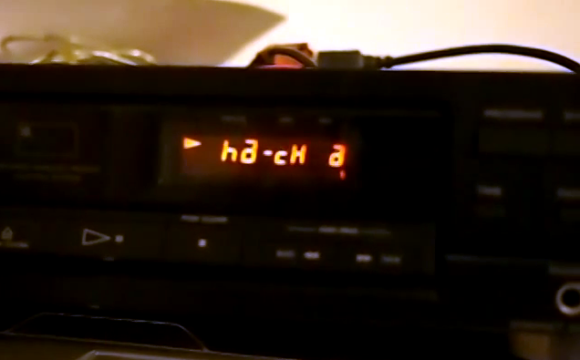
[Ronald] had to scramble to get his submission in, but we’re glad he did. His demo video shows the display of a 1980’s CD player working with Music Player Daemon. It’s really just the original display itself that works, but the project is not yet finished. However, is far enough along to show our URL when a track reaches the 22:00 mark.
The display is driven by an ATmega32 chip which uses a USB connection to receive commands from the computer running MPD. [Ronald] had troubles figuring out how to send int values over USB so he hacked his own protocol that just uses the LSB of each byte coming over the bus. After the break you can see the video, and read the description which he included with his submission. There is also a code package available here.
This is an entry in the Fubarino Contest for a chance at one of the 20 Fubarino SD boards which Microchip has put up as prizes!
The final aim is to have an MPD (music player daemon) based player inside a 1980’s CD player box (working), using the original LCD (working), being able to use the original remote control (working), being able to play DVD’s (work in progress), stuff like that.
My plan is to put the schematics and source on the internet, and submit it to obdev.at because I think it’s a new way to use their USB driver. Because I’m still developing the pc-side software, I hadn’t done yet. I only heard of the Fubarino-contest yesterday, and I thought it would be doable to mod my project, so I did it.
First, I forgot the schematics. They’re quite easy: it’s a general Atmega32 (no ATmega8, since I mostly use those I mistyped it below) HID Bootloader loaded device. Two pins of PORTD are used to drive the back plane. Four out of five 1.1K 1% resistors are used as pull up / down resistors to generate the 2.5V level required for a two backplane LCD configuration.A bit of background. For driving a generic LCD with two backplanes, two square waves with middle value are needed, along with square waves for the segments (e.g. figure 2 at http://www.freescale.com/webapp/sps/site/overview.jsp?code=784_LPBB_LCDTIPS). The timing needs to be precise, to prevent the LCD segments for degrading. Any DC offset large enough can kill it…
PORTA, PORTB, PORTC are all connected to the segments. One additional pin on PORTD is connected to the ‘play’ segment (it seems single backplane), one segment is connected to all ‘off’ segments (I did not have enough pins to drive all segments).
Because I did not know how to send 0x00 characters using USB, I made my own protocol by sending the LSBit of the 2×3 data bytes as the first three of a fourth data byte, and untangle those in the ATmega code. The first three data bytes all have ‘1’ as LSB.
In my project design I decided to do most of the logic on the pc-side, and use the ATmega more or less as a framebuffer. That made it harder for me to mod it to show some text, and to implement the easter egg trigger.
To show the text (the full http://hackaday.com was impossible on this LCD, so I made the closest I could :-)), I used the pc-client first to generate the hex codes of the characters, and then copied those into the ATMega source, modified the LSB’s until it looked well.And that’s about all I can do before the deadline… I hoped to document this all in the code, but ah well.. . It might be enough for you to understand.
The easter egg is in the video at 1:06.
Kind regards,
Ronald


This project totally baffles me. It seems to just be receiving bytes from USB and presenting them to the IO pins. Which is quite simple. And then it’s made MASSIVELY more complicated because “he doesn’t know how to send 0x00 bytes”. Even though, what he’s doing is writing 4 bytes to a buffer on the PC using sprintf() and then passing them to a function that he’s written himself that reads null terminated data and passes them to another function that stores them a byte at a time in a buffer that he then passes to another function that pulls the bytes back out and mangles them into a USB control message with these 4 bytes mangled up into 2 16-bit fields (wValue and wIndex).
Surely, if he can do all that, he could figure out to just pass the values directly in wValue or wIndex? Or send some actual data in the control message? He could actually easily send all the data at once in a single packet if he took a bit of time to read up about LUFA.
It is pretty easy to pass raw binary data back & forth on with
V-USB/usblib. For small amount of data: wIndex, wValue and wLength in
usb_control_msg() could be used to pass integers parameters to the
device. If you are dealing with more data, you can the payload.
I share my header file(s) when I code the host and device. Passing
entire C struct across the different compilers (host vs usb cleint) is
more of a challenge. :)
this competition would be so much cooler if it was a bit like this
http://www.youtube.com/watch?v=FzoXQKumgCw
One would have to hack a device to display messages such as ‘everyone is watching you’, ‘trust nobody’ or ‘they want your brain’
LOL, oh god this is great and horrible, and accidentally hit report, sorry
This project would work better and easier with a Raspberry Pi or a Beaglebone. a lot more IO available and a lot easier to work with. A friend of mine has done almost exactly what this project is, except he just used a 2 line character LCD in place of the stock LCD and interfaced the buttons to the rasPi gpio as well as 4 wires to the gpio for the LCD.
Beaglebone has more GPIO to keep the stock LCD working. Bonus points if you replace the CD drive with a PC drive so you can just drop in a disc and it auto rips. (using a second raspi/beaglebone)
A little clarification to make my work look a bit less stupid… :)
– What was misunderstood by Mike (no problem, my e-mails were a bit messy…) I didn’t use only the LSB’s, I made the LSB of the first three data bytes always 1, and have the fourth byte representing the LSB’s of the first three. I don’t like reading documentation, and do like to do things the obfuscated way and have it work…
– This is a generic (“raw”) LCD, that needs to be driven using constant period square waves, for which I made a controller using a generic ATmega, not an LCD-driver-included one. It’s quite something different than driving an HD44780, even different from driving DC-based LED displays. A Raspberry Pi would be horrible at doing this (at least with the standard non real time Linux).
There’s for my defence… ;)
Anyway @Ralf and @tekkineet: thanks for the pointers. :) I didn’t know it was that easy.
@fartface: actually, there’s a working miniITX computer already inside, IR receiver, 2x 2.5″ drive, and a DVD drive so I can play DVD’s and indeed rip DVD’s. More on the full project will come later…