In our tips line we sometimes receive hacks that are amazing just because of their ingenuity. This relay-powered flashlight is definitely one of them. It has been named RattleGen by its creator [Berto], who apparently often makes simple hacks used in his everyday life (have a look at his YouTube channel).
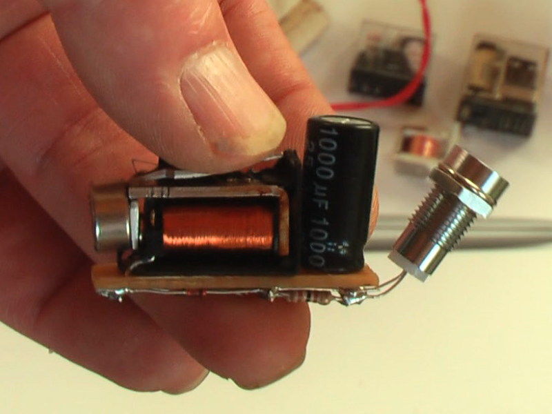
To understand this hack, you first need to know (in case you didn’t already) that a magnet moving near a conductor (here a coil) induces a voltage at its terminals. This is called electromagnetic induction. In the picture you see above, you may distinguish a disassembled relay with a magnet located on the lever’s end. As a ferromagnetic metal is already placed inside the coil, the lever is by default ‘stuck’ in this position. By continuously pressing the latter on its other end, important voltage spikes are created at the coils terminals. [Berto] therefore used a bridge rectifier to transform the AC into DC, and a 1000uF capacitor to smooth the power sent to his super bright LED. A video of the system in action is embedded after the break.


Enocean uses something similar in their product line. This implementation…
http://be.farnell.com/enocean/eco-200/module-electrodynamic-energy-conver/dp/2134178
… harvests enough energy from a push button to power an RF module and send a packet. Their RF modules are comparable to nrf24 or rfm70 in functionality but it has a programmable µC on the PCB.
On a related note, currently working on something similar that converts the movement of an escapement …
http://en.wikipedia.org/wiki/File:Scappamento.gif
.. into electricity. The escapement is wound with magnet wire and has 4 tiny rare earth magnets, two on each side in opposing configuration. When the escapement is in one state the coil is magnetised in one way and reversed in the other state.
That’s really, really cool. Makes me wonder if you could use a larger relay, stronger magnet, and a longer lever arm for a slightly brighter light. Maybe two arms; so you’d squeeze it instead. Would probably get uncomfortable, though, haha.
Interesting use of a relay. Also I wonder if you could use a inductor to smooth the current driving the LED. Using a resistor is wasteful. Kinda the duel of using a capacitor to filter the supply voltage. Although the value for the inductor to provide a constant current may be unrealistic.
The relay coil is an inductor, so that helps. Note the rounded off shape of the pulse on the scope.
The best thing about this nice build is it’s simplicity. Just attach a few things together and you are good. I believe the electromechanical machine would make a better use of the magnet if the magnet was placed in the inner side of the metal piece that moves, however that would require modifying the whole frame of the inductor.
“Then I took a small relay; the output peak voltage of the relay coil was 35 volt, without load”
“The capacitor of 1000 microfarad 16 volt”
Might have just used a 35V part for giggles even if it’ll be a big lower after rectification.
Consider one of those current limiting diodes from a few days ago on HaD.
Solenoid with plunger replaced with a magnet ??
The 35v would be without load, as soon as you add some load (current) the voltage will drop
not a hack, where’s the Arduino? B^)
Ingenious! A true hacker. (though I agree with Bob about the Voltage Rating of the cap).
But wait? There is no raspberry-pi?
I agree with Ren..
Where’s the Arduino? Where, Where I say!!!!! These are indeed dark days in the kingdom…
Great Build
Cool. A voltage doubling rectifier will be more efficient because it only uses two diodes (less drop) (and one can use shottkey diodes)
I’m surprised you get so much from that level of change in flux, cool!.
Yeah though the voltage is already quite high for an LED, it’s probably current it’s short of. It could probably drive a few more LEDs in series with no loss.
The capacitor would likely never be able to charge up to anywhere near the coil output with a load. The LED never sees the HV spikes as the cap filters the output, gradually building charge each time assuming the LED draws less power than the coil. Which I highly doubt could do. If you removed the cap then this may work, but then you only get very short blips of light.
Only requires capacitor and an LED. LED can both rectify the power for storage as well as be used for the light source. Adding more parts like diodes and resistors isn’t necessary and waste power it just requires choosing the correct LED.
I’d like to see how it would go with a small audio transformer on the solenoid output to knock the voltage down.and the current up. That way you wouldn’t loose power over the resistor and possibly be able to run another LED or two.
click click click click click click click click click click click click click click click click click click click click click click click click click click click click click click click click click click click click click click click click click click click click click click click click click click click click click click click click click click click click click click click click click click click click click click click click click click click click click click click click click click click click
give it to people who can’t stop clicking their pen,..then connect them all up to a huge battery and we can power the earth
I just need to find a way to get one in my wireless mouse and Ill never need batteries again! I tend to click aimlessly around the screen when reading….
These things have been around forever
http://en.wikipedia.org/wiki/Mechanically_powered_flashlight
modify for usb charging and call it the minty click?
.. and then sell it for 10x the price.
as well as packaging it inside a smint box (with the click dispense thing) instead of an old altoids tin.
I want one with one of those killer little square CREE LEDs. Probably would need more juice, though…