Magnetic Induction Heats Water

Producing hot water off-grid is a surprisingly energy-intensive activity, and although it looks simple on its surface it can get quite complicated especially when used in large scale for something like providing hot water for an entire home. When using combustion to heat the water there needs to be proper venting as well as control of the fuel, and even storage of the hot water needs to be meticulous to avoid certain pathogens. [Greenhill Forge] has built an off-grid solution for heating hot water that doesn’t necessarily rely on any combustion, though, provided he can find something to spin his custom electric machine.

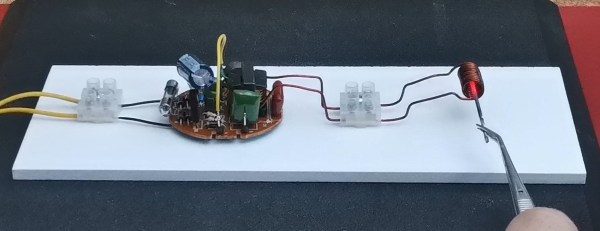
The machine in question is, of course, an induction heater. It works similar to any simple electric motor, generator, or transformer except in this case the eddy currents generated are exploited rather than minimized. Normally these currents, generated when a magnet passes by a metal, are wasted heat in other machines but in this induction heater it’s the goal. The machine’s stator is built from copper tube wound in a spiral which allows water to flow through and absorb heat. The tube is soldered into one electrically solid mass to maximize the eddy currents. The rotor is taken from a previous generator built by [Greenhill Forge] which holds the permanent magnets.

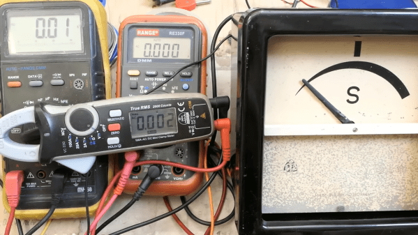
During the initial tests using a power drill to drive the generator, he was able to heat 1.5 liters of water from 7.9C to about 24.4 C in three minutes. The math works out to providing 575 watts of power to the heater, and with something that could spin the generator faster it might have the potential to provide around 14.5 kW. Provided that there’s a source of energy around, such as a wind or water turbine, this could be a fairly sustainable way of generating hot water in off-grid situations. Some of [Greenhill Forge]’s other projects are centered around this idea as well, like one of his builds which uses waste sawdust to heat his workshop with a custom-built stove.

Continue reading “Magnetic Induction Heats Water”

AC Motor Converted Into DC EBike Powerplant

AC induction motors are everywhere, from ceiling fans to vehicles. They’re reliable, simple, and rugged — but there are some disadvantages. It’s difficult to control the speed without complex electronics, and precisely placing the shaft at a given angle is next to impossible. But the core of these common induction machines can be modified and rewired into brushless DC (BLDC) motors, provided you have a few tools on hand as [Austin] demonstrates.

To convert an AC induction motor to a brushless DC electric motor (BLDC), the stator needs to be completely rewired. It also needs a number of poles proportional to the number of phases of the BLDC controller, and in this case the 24-pole motor could accommodate the three phases. [Austin] removed the original stator windings and hand-wound his own in a 16-pole configuration. The rotor needs modification as well, so he turned the rotor on a lathe and then added a set of permanent magnets secured to the rotor with JB Weld. From there it just needs some hall effect sensors, a motor controller and power to get spinning.

At this point the motor could be used for anything a BLDC motor would be used. For this project, [Austin] is putting it on a bicycle. A 3D printed pulley mounts to the fixed gear on the rear wheel, and a motor controller, battery, and some tensioners are all that is left to get this bike under power. His tests show it comfortably drawing around 1.3 kW so you may want to limit this if you’re in Europe but other than that it works extremely well and reminds us of one of our favorite ebike conversions based on a washing machine motor instead of a drill press.

Continue reading “AC Motor Converted Into DC EBike Powerplant”

A man is shown standing in a wooded area, in front of a stone wall, facing toward the camera. To the left of him, on a rock, are a selection of compasses. Further to the left, another scene is shown, of two compasses. One has a brass-colored metal ring around it, and a timer above it reads 00:04:19. A timer above the other reads 01:47:02.

A New Kind Of Inductively-damped Compass

At some point during our primary school careers, most of us probably constructed a simple compass, often by floating a magnetized needle on a cork in a cup of water. The water in such a configuration not only lets the needle spin without friction, but also dampens out (so to speak) the needle’s tendency to swing back and forth across the north-south line. Liquid-filled compasses use the same principle, but even well-made compasses can develop bubbles when exposed to temperature or pressure variations. Rather than accept this unsightly state of affairs, [The Map Reading Company] designed a new kind of liquid-free, inductively-damped compass.

It’s hard to design a compass that settles quickly, even if it uses a strong magnet, because the Earth’s own magnetic field is just so weak, and the stronger the internal magnet is, the more likely it is to be thrown off by nearby magnetic objects. As a result, they tend to swing, overshoot, and oscillate around their final orientation for some time. Most compasses use liquid to damp this, but a few, mostly military compasses, use a conductive baseplate instead: as the magnet moves, it induces eddy currents in the baseplate, which create a weak magnetic field opposing its motion, slowing the magnet down. Inductively-damped compasses don’t get bubbles, but they don’t let you see a map through the baseplate. [The Map Reading Company] dealt with this by making the baseplate transparent and surrounding the compass needle with a ring of high-conductivity copper alloy. This gave him a clear baseplate compass for easy map reading which would never develop bubbles. It’s a simple hack, and should be easy to replicate, but it still seems to be a new design. In fact, [The Map Reading Company] is releasing most of the design to the public domain. Anyone can build this design.

If this prompts your interest in compasses, check out the Earth inductor compass. We’ve also seen a visualization of the eddy currents that damp these oscillations, and even seen them used to drive a bike.

Thanks to [Mel] for the tip!

Using The Wind And Magnets To Make Heat

On the face of it, harnessing wind power to heat your house seems easy. In fact some of you might be doing it already, assuming you’ve got a wind farm somewhere on your local grid and you have an electric heat pump or — shudder — resistive heaters. But what if you want to skip the middleman and draw heat directly from the wind? In that case, wind-powered induction heating might be just what you need.

Granted, [Tim] from the Way Out West Blog is a long way from heating his home with a windmill. Last we checked, he didn’t even have a windmill built yet; this project is still very much in the experimental phase. But it pays to think ahead, and with goals of simplicity and affordability in mind, [Tim] built a prototype mechanical induction heater. His design is conceptually similar to an induction cooktop, where alternating magnetic fields create eddy currents that heat metal cookware. But rather than using alternating currents through large inductors, [Tim] put 40 neodymium magnets with alternating polarity around the circumference of a large MDF disk. When driven by a drill press via some of the sketchiest pullies we’ve seen, the magnets create a rapidly flipping magnetic field. To test this setup, [Tim] used a scrap of copper pipe with a bit of water inside. Holding it over the magnets as they whiz by rapidly heats the water; when driven at 1,000 rpm, the water boiled in about 90 seconds. Check it out in the video below.

It’s a proof of concept only, of course, but this experiment shows that a spinning disc of magnets can create heat directly. Optimizing this should prove interesting. One thing we’d suggest is switching from a disc to a cylinder with magnets placed in a Halbach array to direct as much of the magnetic field into the interior as possible, with coils of copper tubing placed there.
Continue reading “Using The Wind And Magnets To Make Heat”

Robot 3D Prints Giant Metal Parts With Induction Heat

While our desktop machines are largely limited to various types of plastic, 3D printing in other materials offers unique benefits. For example, printing with concrete makes it possible to quickly build houses, and we’ve even seen things like sugar laid down layer by layer into edible prints. Metals are often challenging to print with due to its high melting temperatures, though, and while this has often been solved with lasers a new method uses induction heating to deposit the metals instead.

A company in Arizona called Rosotics has developed a large-scale printer based on this this method that they’re calling the Mantis. It uses three robotic arms to lay down metal prints of remarkable size, around eight meters wide and six meters tall. It can churn through about 50 kg of metal per hour, and can be run off of a standard 240 V outlet. The company is focusing on aerospace applications, with rendered rocket components that remind us of what Relativity Space is working on.

Nothing inspires confidence like a low-quality render.

The induction heating method for the feedstock not only means they can avoid using power-hungry and complex lasers to sinter powdered metal, a material expensive in its own right, but they can use more common metal wire feedstock instead. In addition to being cheaper and easier to work with, wire is also safer. Rosotics points out that some materials used in traditional laser sintering, such as powdered titanium, are actually explosive.

Of course, the elephant in the room is that Relativity recently launched a 33 meter (110 foot) tall 3D printed rocket over the Kármán line — while Rosotics hasn’t even provided a picture of what a component printed with their technology looks like. Rather than being open about their position in the market, the quotes from CEO Christian LaRosa make it seem like he’s blissfully unaware his fledgling company is already on the back foot.

If you’ve got some rocket propellant tanks you’d like printed, the company says they’ll start taking orders in October. Though you’ll need to come up with a $95,000 deposit before they’ll start the work. If you’re looking for something a little more affordable, it’s possible to convert a MIG welder into a rudimentary metal 3D printer instead.

New Possibilities From Fading Lighting Technology

Like the incandescent bulb before it, the compact fluorescent (CFL) bulb is rapidly fading into obscurity as there are fewer and fewer reasons to use them over their LED successors. But there are plenty of things to do with some of the more interesting circuitry that made these relatively efficient light bulbs work, and [mircemk] is here to show us some of them.

Fluorescent bulbs require a high voltage to work properly, and while this was easy enough for large ceiling installations, it was a while until this hardware could be placed inside a bulb-sized package. When removed, the high voltage driver from the CFL is used in this case to drive a small inductive heating coil circuit, which can then be used to rapidly heat metals and other objects. After some testing, [mircemk] found that the electronics on the CFL circuit board were able to easily handle the electrical load of its new task.

When old technology fades away, there are often a lot of interesting use cases just waiting to be found. [mircemk] reports that he was able to find these light bulbs at an extremely low price due to low demand caused by LEDs, so anyone needing a high voltage driver board for something like a small Tesla coil might want to look at a CFL first.

A Look Inside An Old-School Synchroscope

There’s nothing quite like old-school electrical gear, especially the stuff associated with power distribution. There’s something about the chunky, heavy construction, the thick bakelite cases, and the dials you can read from across the room. Double points for something that started life behind the Iron Curtain, as this delightful synchroscope appears to have.

So what exactly is a synchroscope, you ask? As [DiodeGoneWild] explains (in the best accent a human being has ever had), synchroscopes are used to indicate when two AC power sources are in phase with each other. This is important in power generation and distribution, where it just wouldn’t be a good idea to just connect a freshly started generator to a stable power grid. This synchroscope has a wonderfully robust mechanism inside, with four drive coils located 90° apart on a circular stator. Inside that is a moving coil attached to the meter’s needle, which makes this an induction motor that stops turning when the two input currents are in phase with each other.

The meter is chock full of engineering goodies, like the magnetic brake that damps the needle, and the neat inductive coupling method used to provide current to the moving coil. [DiodeGoneWild] does a great job explaining how the meter works, and does a few basic tests that show us the 60-odd years since this thing was made haven’t caused any major damage. We’re eager to see it put to the full test soon.

This is just the latest in a series of cool teardowns by [DiodeGoneWild]. He recently treated us to a glimpse inside an old-ish wattmeter, and took a look at friggin’ laser-powered headlights, too.

Continue reading “A Look Inside An Old-School Synchroscope”