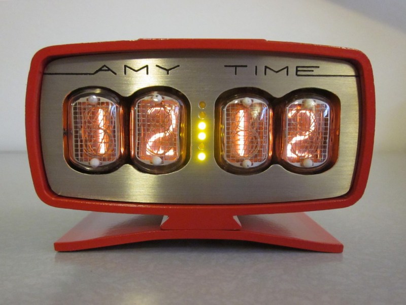
[Reboots] is a humble hacker who enjoys nixie tubes. So when he saw an old General Electric battery charger for sale at a hamfest, he thought: “that case would make a nice clock…”
He was first exposed to nixie tube clocks a few years ago when his brother gave him a DIY nixie clock kit from [Peter Jensen’s] website TubeClock.com — it was an easy build, and worked very well. It also introduced him to a unique driver for nixie tubes, an HV5622 high-voltage shift register made by Supertex inc. Compared to the traditional (and rare) 74141 nixie driver chips or discrete transistor drivers, the HV5622 is much smaller, requires less microcontroller I/O’s, and is not as picky when it comes to powering it.
The nixie tubes he chose for the project came from a lot sale on eBay, Russian surplus IN-12 tubes. He even managed to find an english datasheet for them!

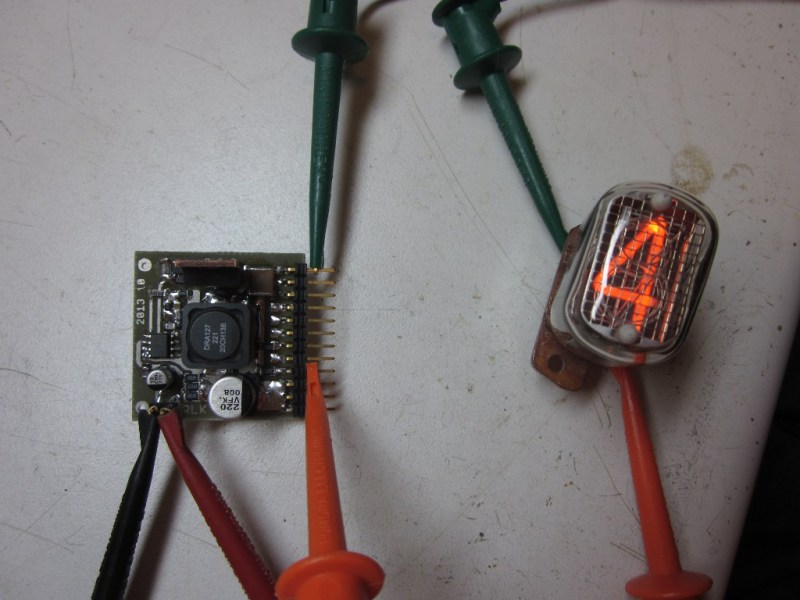
Having decided on the nixie tube, driver, and case, he now needed a reliable power supply. Threeneuron’s design fit the bill nicely, however it ended up being a bit noisy under load, but [Reboots] notes that the TubeClock kit used a free-running transistor oscillator, which was in fact even louder under load!
From there it was a matter of testing the tubes, prototyping some PCBs, and programming the ATmega48. Simple, right? Nixie’s are never that simple. But lucky for us, [Reboots] has an amazing build write up on his site, so if you’re interested in learning more, take a look!
Oh, and if you’re looking for a really unique nixie clock — why not build one without a PCB entirely? Just don’t touch the high voltage lines…


That looks really nice.
Only question is why the green LEDs, when red would have matched the nixies and the enclosure?
Or small neon bulbs, the voltage is there already. Very nice build.
Or orange LED…
Sweet, looks like George Jetson’s alarm clock.
I wonder if Alcoa extruded that stock, could have been railing. Great mid century look.
If you find another make it a tiny widescreen TV monitor!
Have been wanting to build this nixie clock for years. On my off time, have scoured eBay for this GE charger. Still no joy. Never thought of an extrusion possibility. Yet another avenue to search. Does anyone know of a charger model number or extrusion number?
George
Dorge again!
OMG, I found one! The GE Charger model # is 4EP34A10. Finally a searchable number!
Dorge
Love it, but like said above, NE2’s instead of LED’s would have made it over the top.
Pure Awesomesauce.
“Additionally, the prototype PSUs used 2.2uF 250V MLCC capacitors; I substituted aluminum electrolytic out of concern for MLCC longevity.”
Since when do aluminum electrolytics have longer life than ceramics?
No so much on long longevity, but I can see reliability issues. Large
MLCC packages has lots of mechanical issues – cracking/plating tearing
off due to mechanical stress associated with shock/vibrations/
temperature expansion coeff. mismatch etc. 1210 is about the largest
package I would use.
There are feedback loop stability issues if you blindly substitute caps
(usually from Electrolytic to ceramic) without understanding their
effects of their ESR to the feedback network for older regulators.
If you keep the good quality Al electrolytic caps cool (i.e. don’t put
them next to heat source, keep ripple current low i.e. self heating low,
use a larger package if possible), they would last a long time.
I like this clock. It has a retro-futuristic vibe that just works. This clock would not be put of place on one of my shelves or next to my desktop monitor.
I keep coming back all day to look at this! It looks very nice :)
Another vote for a “thumbs up” button for HaD postings!
Amen!
*sigh* Kids these days.
To be fair, Kids are how they are mostly due to how their parents brought them up… so *sigh* parents these days… :-)
It was the internet’s fault.
This is awesome! Easily top 10 HAD material. Love it!
Hello, HaD! Thanks for the kind comments!
Peter Jensen sent me a friendly email this morning to help me diagnose the sound I was hearing from his kit, and offering to send a replacement inductor. I think my comparison to his design was hastily-worded and ultimately irrelevant, so I’ve removed it from the writeup.
@ChalkBored, et al: I compared several types of orange and red LEDs against the tubes. They didn’t look right: like a match was intended, but just didn’t work. I decided to go with striking contrast. NE-2s would definitely be more complementary, but would be shorter-lived (no mercury added) and harder to replace than the socketed tubes. Authenticity wasn’t the goal; the clock evokes past style, but is meant to represent the present and the future. (And it’s already full of high-tech silicon.)
@tekkieneet, thanks for articulating my concerns re: MLCCs. I think the 2.2uF 250V caps I used initially are flexible-terminated automotive types, but I don’t know how hand-soldering affects their reliability. High-value MLCCs are also microphonic, have poor temperature stability, and high ESR (although those characteristics didn’t matter for this application). And they’re expensive. MLCC technology is impressive; it’d be great if it were a magic bullet to put aluminum electrolytic and (especially) tantalum out to pasture. But it’s not quite there yet for many applications.
Actually that’s a good point on hand soldering and reliability. A lecture from Kemet that I went to outlined that they’d done studies that suggested that hand soldering was virtually guaranteed to cause internal fractures in any package size larger than 0805 (that is, if the solderer is careless enough to touch the device terminals with the iron).
Still, disregarding mechanical stresses (made less troublesome with soft-termination parts), good ceramics should outlast electrolytics by one or two orders of magnitude when exposed to the same environmental conditions.