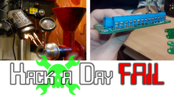

This Fail of the Week is a twofer. On the left we have an attempt to heat the output of an oil expeller. After a bountiful crop of sunflower seeds [Mark] picked up the oil expeller to make is own cooking oil. He tried to use the soldering gun as a heat source but after just a couple of minutes of on-time it melted the soldering iron’s plastic case. He’s looking for an alternate heat source but we wonder why he can’t just ditch the plastic and bolt this to a heat sink?
To the right is the product of hasty PCB layout. [Andrew] needed a USB to GPIO converter to use with his Android stick. He had built several of these before, etching the PCBs himself. But now he didn’t have the time to do his own etching and figured he could lay out a revision of the board and have it fabbed. Turns out this isn’t the time saver he had hoped. Problems with the location of silk screen labels aren’t a huge deal, but the ‘V’ in the board where his USB connector is located blocked any cable he tried to plug in. A bit of cutting solved that but he also had to deal with spring terminals whose leads wouldn’t fit the diameter of holes drilled in the board. We always print out the Gerbers and compare the footprints to our parts before submitting to the fab house. But we’re not sure we would have caught the USB cable clearance issue doing it that way. What checklists do you use before submitting your own boards?
 Fail of the Week is a Hackaday column which runs every Wednesday. Help keep the fun rolling by writing about your past failures and sending us a link to the story — or sending in links to fail write ups you find in your Internet travels.


Fail of the week for PCB with silkscreen and clearance problems…. And you guys use MANUAL checks against the gerbers??? Do your tools seriously not have DFM or DRC checks??? Time to move tools. You get what you pay for, by the way.
Depends on the board. For a huge boardI’druna proper DRC. For a small one a good look on the board is usually faster…
Well, when you are in a terrible hurry both don’t work out.
Or use kicad, it does drc while you are laying the signals
So you tell me that there are still tools that don’t offer live drc checks?
Actually, I did use kicad for that screwup above.
DRC only works as good as the person who wrote the Rules. IF you dont account for it in the rule definitions, The software wont check for it. Compared to an expensive cad package, KICAD’s DRC is kind of lacking, but I agree with the above poster about checking through a small board carefully rather than writing complicated Design Rules. With a complicated Altium design for example, you could spend nearly as much time setting up the DRC as Laying out the board! I usually use the paper printout method to verify a lot of my stuff, and I never take a prefab footprint at face value! Paper printouts usually wont catch holes that are too small though! Depending on how you spec the holes(finished or drill size only), the board house may drill to your specified size, and plate them afterwards, making them too small if they are marginal to begin with. Not a terribly uncommon mistake, and I have been bit by it too!
DRC would have caught silkscreen over solder pads… but that’s about all. A visual check of the top/bot layer with its silkscreen overlayed is about the only thing that would have revealed silkscreen placement issues.
The datasheet for the screw-terminals should have had drawings describing the minimum hole diameters for the pins. Alternative – got terminals? Measure them.
Placing the USB connector at the edge of the board wouldn’t have required the extra board outline cuts – it would have been simpler, it would have worked, and maybe even have been cheaper. (Only USB1.1 devices have removable cables. USB2.0 and later forbid such cables – they are connected by soldering to the board, or by an internal, unremovable board connector. Should have soldered and tie-wrapped the cable to the board.)
Bottom line – the layout was way too rushed, and not well thought-out or researched (probably needed 2-4 times as much time as actually spent). I suspect the designer wasn’t familiar with the tools, or experienced with board layout. Small, simple boards like this are for learning these things.
Now go back and fix the boards, even if you never plan on having these boards made again.You need the experience.
I may have gotten the removable USB cable comments wrong.
Yes, i have two external hard drives, usb 2.0 and 3.0, both with detachable cables. One thing is they are very short and much more robust than the rest.
It would if you create a DRC rule for that. Altium has one by default.
Make his own.
Oh good grief, He should have known that those type of soldering guns have a short duty cycle and are not designed to be on for more than a minute or two max.
The maximum on time is usually printed on the side of the gun.
Would it be too difficult to control the heat output from an induction coil?
you can still save your soldering iron by unplugging it first (electric and water not good)
then dunk the iron into a bucket of water to cool it then shake the water out before you use it again.
Are you kidding! The water in the coils will cause breakdown of the insulation for sure. Any dunked stuff with transformers should be air dried with gentle heat and moving air for DAYS before testing then deployment. The soldering gun in the article is a piece of foreign made crap, I have gone elsewhere when one of these is all that is around to do a repair. The Weller 100-140 watt iron is the standard you can’t live without. I do printed ckt work with these (trigger control) never burn traces just goes to work in 4 seconds. Then for soldering to a steel chassis you need the big gun the Weller 250.
I don’t know how much heat is needed but a wraparound industrial heating element is needed in the press. Less than 10% of the heat of this gun is going into the press head.
I had a Weller solder gun and that melted/cracked from the heat too so that this was “foreign made crap” had nothing to do with it. That solder guns – even heavy duty ones – aren’t made for long active periods is the reason.
Solder guns aren’t exactly high tech and if it works it can’t really be crap. It’s a transformer with a switch attached, pretty hard to screw up. What can be crap on these: the solder tips. Without the proper protective layer the life time is tragically short.
If anyone knows of a reasonably priced solder gun that can sustain at least a 25% duty cycle without melting please let me know.
Just add a fan. You still won’t be able to use it constantly but it cools off much faster.
DRC, etc doesn’t work if the parts outline, pad/hole sizes are wrong to start with.
I take a part ‘puppet’, adjust the dimensions, etc and then save it linked to a specific part # – the screw terminals can come with several pin diameters/sizes – eve if the part is a physical size equvilent – been there, been burned by it also.
Wouldn’t using a large wattage ceramic resistor work better then a soldering iron, I know they use something like a 1.5 ohm 5 watt resistor in the boot dryer I have
Dale Resistors with the little mounting tab feet work wonders as heating elements. We use them for certain applications that require enough heat it will burn you and they last for years. You just choose the right resistance for the wattage you want (and not to exceed the rated value, of course) at the power supply voltage you are using. A temperature controller would help too.
Nothing beats a good review of the *gerber files*, since that’s what the manufacture is going to build. If you think KiCad is going to catch everything I suggest calling the manufactured after they build the boards to ask for the “as built” files. It could be a real eye-opener. DFM rules against the design data are a very different thing than DFM against the gerbers, et. al.
Before I etch a board I print it on paper, put the printout onto a piece of foam, and stuff the paper with components. Then I have a mock up of the physical board to check out clearances.
Never thought of that, Thanks pcf11!
I’m dumbfounded that your solution is so damn simple yet saves so much headaches. /awed
Watlow makes all sorts of ring type heaters that clamp on whatever you want. They are cheap.
You can get burned with Eagle on silkscreen labels. All fonts need to be VECTOR to show accurate locations. Proportional looks nice, but doesn’t come out well in Gerbers.
I’m unfamiliar with what’s going on with this particular oil expeller, but I thought the point of a good expeller is to avoid warming the oil, because warming the oil tends to spoilage. The blog didn’t seem to hint at the motivation.
Heating the oil will make it react with oxygen causing faster spoilage. This is not that important of a problem provided you limit the air contact of the oil and or the time it is heated. For canola oil at least it must be heated to deactivate the enzymes that will spoil the oil. In the canola crush plant I work at we heat the seeds to around 90 C and keep it there for around half an hour.
The motivation to heat the expeller is really to heat the seeds (A heating element in the feed hopper might be a better idea) as warm seeds will require less force to crush, and will expel more oil.
I print everything to paper and then layout all my components.
I’ve found this set of micro reamers really helpful for dealing with under-sized PCB holes. It also helps fitting thick-lead components into standard perf-board.
Be carefull, FR4 does a very good job at dulling edges.
Given the layout, I would first flip the board upside down so that the
majority of the traces (except 2) are on the solder side. I would drill
out those holes to fit the terminal block. If your pads are too small,
then you are SOD.
You would need to remove some of the solder mask and solder fine wires
to patch broken pads or those other 2 traces.
the oil expeller is made of metal, so you COULD make an induction heater for it :)
Through hole plating thickness isn’t always consistent at budget PCB fabs. Screw terminal lead diameter may not be consistent between manufacturers either. The very first thing I did in Eagle once I started using screw terminals, is edit the models to make the holes bigger than a measured lead of a terminal I had on hand. Upon receiving my first batch of boards, I realized maybe I went a bit overboard. ;) But other than looking a little silly, no harm done, too big is better than too small.
No experience… I would probably print it out on paper and hut glue it to florist’s foam and them simply punch the through hole components into the foam through the template >_> If you criticize me I will bash you with my caveman club :P
a nice summary:
https://www.youtube.com/watch?v=BZBWhLZx50Q
i spend a fair amount of time working on my eagle library. containing a couple of 100 devices, i have a status for each of them, telling me which has been tested in real live, for diy and pool pcbs, etc. i use keepout and restrict in combination with either my own drc (parameters i know i can handle), and drcs provided by board houses.
final check often is made by printing each layer and test placing parts. esd sensitive devices i used for test placing get a white dot and will not be used in critical designs anymore. this may seem a little paranoid, but for now i have to say i’m happy.
0.5mm pitch smds, 0402, qfns etc on self-etched pcbs (using a led exposer i once built) are totally possible