How many power bricks have died on you? Have you ever tried to fix them? Sometimes it’s easier to grab another one (they grow on trees right?), but wouldn’t it be nice to save the broken ones from filling up landfills? Depending on the cause of death, it could be a super simple fix!
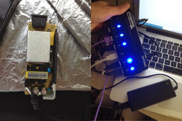
[Chaim-Leib] recently purchased a powered USB hub that came with a beefy 5v, 4A power supply — it worked great — until 6 months later, when it didn’t. The company sent him a new one, and let him keep the faulty one. Looking for a challenge, [Chaim-Leib] decided to crack it open and see if he could fix it himself.
No burnt caps, no fried diodes, no burn marks anywhere in fact! Luckily he spotted the culprit: One lonely resistor had lifted up from its pad. Having never jostled or dropped the power brick, this failure likely came from some kind of stress formed during original assembly — throw in a bunch of hot and cold thermal changes, and pop goes the solder pad!
It was a simple fix with some solder, and he emailed the company photos of his operation — they’ve promised to send them on to the engineering team to further evaluate the problem.
That was easy.


interesting!
however, what makes me wonder, is the comment of forwarding the pictures to the engineering team, as things like psus more often than not are bought in bulk.
That’s an excellent point Luke! It is quite unlikely that Plugable manufactures the PSU’s themselves…
Clearly they buy the PSUs though. If their engineers evaluate the problem and decide it’s a real problem, they could buy the PSUs (in bulk) from someone else.
How is that suspicious? Granted, they may not actually do any of that, but there’s no reason to think they couldn’t or wouldn’t.
meh whatever, they have a cable i need. looks like this whole thing made me a future customer. discussions tend to attract me more than adverts. weird.
I work in a similar industry.
While we don’t have “engineers” ourselves, we can forward concerns like these to the manufacturer/OEM, especially if we have a number of similar cases.
Clearly this is one of those boards that are soldered by chinese low-paid workers who need to do one board in 15 seconds or they get shouted at or fired
Noticed the large ‘made in china’ on the first picture btw?
“he emailed the company photos of his operation”
That’s a fair trade for a free PSU.
I wonder how many PSU’s I could snag with photos of my aunt’s hernia operation.
Besides the cords going bad, the only power brick that’s died on me was from a Commodore 64 back in the 80’s.
And that children, is what happens when lead-free solder is used.
A multi-million dollar company being out shipping and the cost of a power brick is somehow less troubling than the environmental and social impacts of lead to me.
Not that long ago lead was used in pipes that provided drinking water and utensils for eating and drinking. Lead compounds (much more dangerous than lead itself) were pumped into the air from cars which burned leaded fuel. It even was in the paint that coated the insides and outides of our houses, eventually finding it’s way into the dust people breathed.
Demonstrating that the old kinds of lead use had “troubling environmental and social impacts” is a long way from demonstrating that leaded solder has any impact. Sure, it’s been proven that that was bad but how do we get from there to virtually no lead in anything?
While certain lead compounds may be scary metalic lead does not simply disolve into your skin just by handling it any more than other metals. Did you know that copper and nickel are toxic? Even gold can be toxic as a chloride salt. What happens if you get table salt on jewelry?
Lead isn’t contained in the smoke coming off of a soldering iron. It would take much more heat than that to vaporize lead, the smoke is just the rosin. BTW, the rosins used in non-lead based solder are usually much more toxic than the rosins used in lead based solder (basically pine sap).
I don’t know about everyone else here but I don’t eat or drink off of my PCBs. Neither do I burn them and inhale the fumes.
Maybe some people are concerned about what happens at the landfill when lead based electronics are eventually disposed of? To that I ask this… does it really make things any worse? It’s not like landfill leachate is nice stuff with or without leaded solder. Either way it needs to be contained and kept out of the water supply or there will be problems.
Similar to: In our laboratory, rats developed cancer, after we injected them daily for 3 years, with an artificial sweetener equal 150 cans of soda. Therefore we have definitively concluded the artificial sweetener will cause cancer in humans and must be removed from all consumption and anyone who has consumed even a small amount of this substance needs to contact lawyers for a class action lawsuit to sue the soda companies, the manufacturer(s) of the sweetener, grocers that sold the soda, the transportation industry and the mining industry which may have mined raw materials for the manufacturer(s).
“-LESS- troubling -THAN- the environmental and social impacts”(emphasis added for clarity)
E-waste is but one way lead gets into the environment. There’s also the mining and smelting processes before we get that lead to the soldering iron.
Sure lead isn’t that hazardous but the effects are cumulative. It’s also easier to prevent hazardous waste spills by not generating hazardous waste. Like I brought up before if the effects of lead-free solder are 1ppm joint failure and the cost is carried largely by the manufacturer, it’s worth it to me.
The break was between the copper pad and the PCB, so it’s unlikely to be the result of lead-free solder. More likely, the resistor wasn’t pushed all the way down on the board before soldering, so all the force of shock and vibration would be applied to the weak bonding layer between pad and board.
also, from what I can see on the pictures, this is the kind of damage that often happens to single sided, not plated-through pcbs. especially, if there was above average heat stress.
switchmode powersupplyes can be tricky to repair, but it can be done. I found a great video that expalin how a standard switchmode as shown in this post works. It is called a buck converter. You can find a schmatic and the video here:
http://translate.google.dk/translate?sl=da&tl=en&js=n&prev=_t&hl=da&ie=UTF-8&u=http%3A%2F%2Ftechmind.dk%2Farduino-singleboard%2Fbuck-converter-forklaret-switchmode%2F&act=url
It describe a DIY buck converter that can be very easy build
every self respecting hacker should learn how switch mode supplies work. i did and its something i have found very useful in all my electronics projects.
best way to learn is to build a 555 based switch mode regulator. mine had an opamp in comparator mode to compare the output with a zener reference, then i would use an and gate between the switching signal and the comparator out. and its output toggled a power mosfet. this gave me dead on regulation. this circuit worked pretty well in both buck and boost modes, i played with buck-boost to create negative supplies as well.
my first one could push 500ma. once i figured out all the maths, pushing a couple amps became second nature. only then did i treat myself to some of the more purpose build switch mode chips (with the power transistor, and much of the feedback logic built in).
Agreed. I’ve never built a switchmode PS, and maybe I’ll never need to. But I at least practiced in SPICE until I was competent designing one using an LM339 and discretes. Although SPICE isn’t perfect, I learned a lot, and fast. Programming is my main background, purely digital. This and many other similar exercises really improved my overall analog skill, which was sorely lacking.
To all, see if you can SPICE up a similar switching power supply in an evening or three. When you get something that appears to work, start testing it against various resistive and capacitive loads, momentary short circuits, input voltage ripple, and any other contingency you can think of. See if you can make it stable and smoke-proof under all these conditions.
And then if you master that, pick something else and try to do it too. My last two exercises were a linear audio amp that’s stable despite possible transient and capactive loads, and a linear voltage and current controlled power supply. As a handicap I did both without using any existing designs as guides. The amp was posted on a forum for peer review, someone said they’d never seen a topology like it, but it looked fundamentally sound. Was very satisfying to hear that.
This looks like another example of “buy them so cheap we dont care if they are defective because we can just send out replacements”
Anyone tried to load a brick to its “rated” capacity? They usually duck down to about half or less of their rated voltage when loaded down to rated current (I suspect partly because the ratings are at 240V)
I’ve loaded a few to near rated capacity, powered by 120VAC. They performed fine.
One has an interesting quirk with anything bigger than a 10uF load capacitance, in that the overcurrent protection kicks in and the PS shuts down, then resets, repeatedly before the capacitor finally becomes charged and the PS operates normally.
Of course, these were all REAL bricks. Brand name stuff, salvaged from brand name gear, most many years old. Not some of the extremely dodgy stuff I often see passing for power supplies nowadays.
I’ve fixed about 7 laptop PSU’s. 99% of the time it is one of two things. The barrel jack on the cable or motherboard, or a short in the DC side of the cable. If your dog or cat chewed on it, it’s easy to spot, if not then it’s usually right where the cable connects to the PSU motherboard on the DC side.
All of the PSUs cases I have worked on were glued together, the best way I have found to open them is to take a wide Flathead screwdriver (1/2in) place it on the seam in the middle of the long side and smack the heck out of it with a hammer all along the seam. If you worry about hurting the case you can hit it with just the hammer to loosen the glue, it works just as well, just takes longer. You really have to lay into these things to open them, even if you break them they are only 15$ on ebay. Only once have I broken something inside one (toroid, just soldered it back on.)
To comment on PSUs manufacturing issues, I have run into a Toshiba PSU with a loose resistor, and broken solder pad. I also found that the motherboard had a light on it but not a view port on the outside of the case? So I drilled a hole to see it.
lol
i usually tape the damn leds on power supplies with the protective film of photo sensitive copper clad board. it drives me nuts when in bed
I’m curious, why not just use an ordinary piece of electrical or masking tape?
Probably because he has plenty of the other stuff left over, which would otherwise end up in the trash.
that is actually the main reason. when exposing pcbs i stick the protective film to any nearby clean and flat surface. in case of double sided pcbs i expose and etch one side, drill two 0.3mm holes for alignment, expose and develop the second side, stick the film back onto the first side and then etch side 2. but in many cases i end up with loads of this film/foil which really does a great job in hiding leds.
i have no electrical tape at home, because i dislike the disgusting mess it produces.
it can be cleaned up with wd40, but that’s why i avoid that stuff.
I use a chisel that the previous occupant has kindly left behind to crack those cases. It works great! :)
As for darn bright LED, I use those polyimide “yellow” tape on top of the case, then a permanent marker with the right colour absorption dye and then another layer of tape. This attenuate the light enough, but still let me see it.
As for polyimide tape, they use glue that doesn’t screw up surfaces nor turn sticky and yucky over time.
Yeah, there is no EASY fix for PSU. ever.
opening those things will destroy the case. always. it is a pain in the ass.
I love Pluggable. I learned about them when I looked for a Bluetooth dongle.
They had the best documentation, even for such a jelly bens part. And they have a Linux compatibility list for their products. Where they don’t just tell you if it is supposrted, but also since which Kernel version.
Bought a few things from them since. And liked it.
switch mode supplies are loaded with cool parts anyway. even if i dont fix them, i at least salvage all the power components.
One thing, Never EVER use a glue gun to seal things that:
A: could get warm, and
B: could harm people if it accidentally falls open, or
C: that you actually want to stay sealed.
Hot glue gets very soft at temperatures far under the melting point, it also has a tendency to suddenly lose grip and fall off.
Hot glue is good for filling and temporary joints.
Yup, everyone should know that duct tape is the right way to go.
It depends on the hot glue. I use a commercial grade white hot glue and it sticks to just about anything and never lets go. I literally have to cut it or pry it free.
Please don’t ask where I got it or what brand it is. I’ve had it for over 10 years and I have long since forgotten it’s source.
Helpful, huh?
It could be hot-melt silicone, like;
http://www.dowcorning.com/content/design/designmaterial/hot-melt_silicone.aspx
Once cured, it’s about as good as any other silicone.
Otherwise, McMaster (as always) carries many different hot melt glues, though the advice not to use them for things that get warm is good.
Stuff you don’t need fixed is always easy to fix. The stuff you want to fix never is easy to get going though.
I never had a a “brick” power supply fail on me, but repaired a few other switchmode PSU’s. (UC3842 or similar driver chips)
They are usually not hard to repair. Mostly output filter capacitors gone bad, or the “startup resistor”. Troubleshooting can be a bit of a challenge with live parts, but some can be run from 30VDC primary. (They wont start from 30VDC unless you lower the startup resistor temporarily)
Good info on SMPS repair: http://www.repairfaq.org/sam/smpsfaq.htm