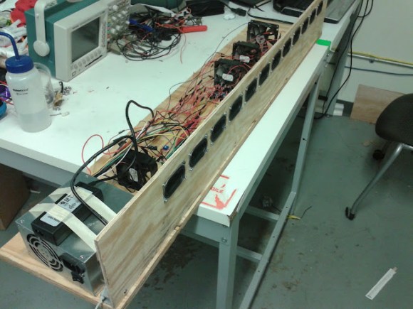
[Edward] and [Tom] managed to build an actual phased array speaker system capable of steering sound around a room. Powered by an Atmega 644, this impressive final project uses 12 independently controllable speakers that each have a variable delay. By adjusting the delay at precise intervals, the angle of maximum intensity of the output wave can be shifted, there by “steering” the sound.
Phased arrays are usually associated with EM applications, such as radar. But the same principles can be applied to sound waveforms. The math is a little scary, but we’ll walk you through only what you need to know in case you’re ever in need to steer sound with a speaker and a servo phased array sound system.
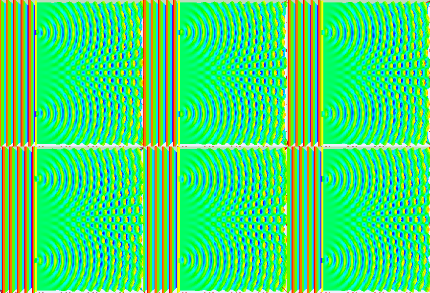
The physics of a phased array system can be demonstrated with a diffraction grating.

The above animation shows what happens to a waveform as it passes through openings in a barrier. By counting the number of openings, obtaining the distance between the openings and combining this knowledge with the properties of the incoming waveform, one can find the area of most intensity.

This is the phased array setup. If you consider each speaker as openings, you can apply the same technique. [Edward] and [Tom] hammered it out, and found that the output intensity can be calculated by the following equation:

Where vs = speed of sound, d = distance between speakers, and td = a time delay. By varying the time delay, you vary the angle of maximum intensity. [Edward] and [Tom] tested their theory in MATLAB, and it worked!
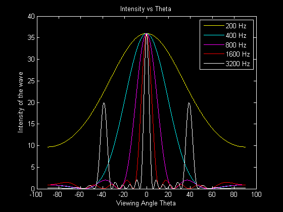
Below is the theorized output of several frequencies with no delay.

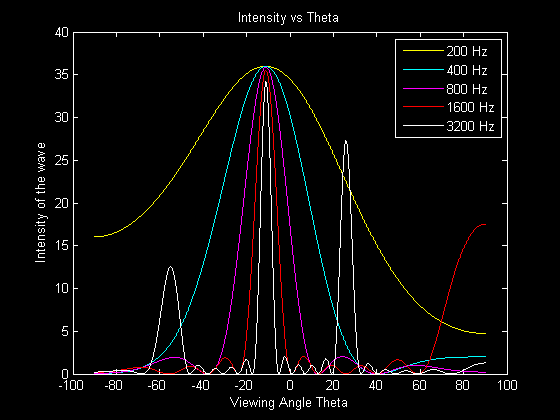
This is the output with a .3ms delay.

Be sure to check out [Edward] and [Tom’s] project for complete details, source code, schematics, ext. Below is a video showing the project working in real-time.


Sonar anyone? Yes I know subs has used devices like this for many decades but maybe for a robot?
In addition to steering the sound as described in the build you could focus the sound at a certain distance from the speaker array but delaying progressively from the outer speakers to the center one (with the greatest delay) . Changing the delay to change the distance.
This is fundamentally the way ultrasound imaging and steered Doppler works. There is a flat transducer with many pizeo elements that are fired with delays to focus the beam of sound for imaging or angle it for steered Doppler.
Hmm, does the same formulas work backwards for microphones? Or how much more code does that require :). It would be fun to have an array of microphones and extract n distinct sound streams, isolated by their location rather than frequency.
Fundamentally yes, this works in reverse to figure out where sound originated from. In the simple sense, that’s how your hearing works. You work out from when you hear the sound at the various locations the angle the sound occurs at. You have to come up with the fast matching to locate sound captured at one mic and locate the same sound on the other mics. As you noted, you have to isolate each sound from the others, a non-trivial task. Single frequency pulses, where everyone plays nice, stays on a single frequency, and you can use simple FFTs to break them apart, then figure out when they arrive at each mic. Reality is that you have something closer to noise, and you have to correlate what might match up (guess), then see if the guessed original sounds appear on other mic inputs. Just figuring out what sound is from a single source it a huge problem in itself, figuring the angle it trivial once you have figured out how to separate the various sounds.
Yes it’s possible. All those antenna arrays (e.g. LOFAR) use this principle. The difficulty doesn’t lie in “how much code”, but “what kind of mathematics”. But you can do some fun things with it, like recording the inputs and “pointing” the array at a later moment.
http://sourceforge.net/apps/mediawiki/manyears
Check out http://www.sorama.eu , they make a 1024-channel MEMS microphone array. The thing was used by some of my fellow students to create an interactive sound-location visualizer ( https://vimeo.com/78977964 ).
http://hackaday.com/2013/06/09/echolocation-pinpoints-where-a-gunshot-came-from/
Correct me if I’m mistaken, wouldn’t you have to set different delays for different frequencies to correctly direct the complete music frequency range?
They manipulated the math to get something that would work for all frequencies. They said that phase / frequency was equivalent to a time delay, but did not elaborate on this. They we’re not sure it would work, but verified it in matlab.
I’m nearly certain that this is not the case. Note that every tone in the graphs shares the same fundamental. If the checked spots in between there, they would find some nulls.
Something else I forgot: all of this is actually used in designing line array systems and subwoofer arrays.
Or instead of all that math, just sample complex amplitudes for each of the emitters in the array and then perform the FFT, change the phase to account for the new direction and perform the inverse FFT.
http://en.wikipedia.org/wiki/Angular_spectrum_method
Yep, they talked about this as well, but thought the Atmel would not be able to handle the FFT calculations fast enough.
One time I was looking to the TMS320C5535 for a particular project.. (keyword FFT)
http://www.ti.com/ww/en/embedded/c5000/index.shtml?DCMP=dsp-c5000-c553x-110830&HQS=cheapdsp
By the way… the same method can be used (inversely) to get the direction of a travelling wave (if you replace the speakers with microphones, that is).
Okay, high end use for this idea…On the shoreline with lifeguards. Let them use directed commands to swimmers going out too far and looking for trouble.
Hate to burst your bubble. The life guard can simply point his/her speaker phone toward the direction he/she wants. But you can always ask: “what is the fun in that?”
Very interesting project for sure, I just wonder how noticable the effect is? I don’t think it would be as though there is no sound when the main lobe is steered away from you to deafening when it is… it would be like playing with the pan knob on a stereo system (remember those days?) or a phase shifter guitar effect. And as someone pointed out and is is apparent in the spectral analysis above, frequency is a factor, as each band would need to be shifted a different amount. You could probably strengthen the effect by splitting the sound into sperate bands via a filter array and then shift them individually before brodcasting.
The video doesn’t do justice to the steering, because he’s too close to the array and in a closed space…if they were outside and at least 2-3 meters further, the difference would be significant…
p.s. this is a much better animation explaining the phased array: http://www.radartutorial.eu/06.antennas/pic/if3.big.gif
I wonder if some styrofoam could help visualize the steering. Or just make a complete mess if blown all over :).
I was in a museum the other day and they had a flat speaker that directed the sound towards the viewer of a video screen. And at TED I saw a similar device that was able to direct sound at one particular person in the audience. I think it boils down to simulating a parabola shaped transmitter…
It’s just a PWM or AM modulation of an ultrasonic (40 kHz) transducer with low-pass filtered audio. The non-linearities of the air will cause it to demodulate. The expensive devices use DSP to “pre-distort” the signal so it sounds much cleaner. An example is the “Speech Jammer” from a while back:
http://blockyourid.com/~gbpprorg/mil/speechjam
https://www.youtube.com/watch?v=HF9G9M0cR0E
Actually, there is at least one company I am aware of commercially producing focused arrays based on this phased array principle which targets museums and other such venues. They boast some pretty high-profile installations, for example the Country Music Hall of Fame. I got a tour of their production facility years ago when I was in middle school; the guy who runs the company is married to my then English teacher. http://www.dakotaaudio.com The demo was pretty awesome; I was astounded at how well these things worked.
interesting, the hardware looks very much like a wave field synthesis setup, although the goal appears to be different.
Whereas WFS uses the speaker array to simulate sound waves originating at virtual locations in a 3D space, this project focuses more on the effect at a certain point in front of the speakers.
When I clicked on the Wikipedia link for Phased Array I found an interesting reference to using sound phased arrays, like this one, but with more speakers arranged in a grid, for producing “tactile feedback” for holograms, check it out, its a cool idea.
http://www.alab.t.u-tokyo.ac.jp/~siggraph/09/TouchableHolography/SIGGRAPH09-TH.html
Hmmm…. SAR applied to sound never occurred to me. Excellent thinking!
Applications… hmmm.. haunted houses. Ohhh… I got it! A new way to screw with the squirrels in the yard! Furry little things, should be able to give them the impression they’re being petted! Neighbors cats too!
As for a practical application, maybe get rid of that groundhog for good.
We use this principal in non destructive testing a lot.
http://en.m.wikipedia.org/wiki/Phased_array_ultrasonics
Works very well and is sometimes used instead of radiography. Would elaborate more but replying via phone.
Calcs show may be able to keep it sub-audible at 30 ft and seem like your hair is being stroked.
I’m stoked!
http://www.renkus-heinz.com/steerable I get to use the IC-live version. Very cool.
I agree with tjbaudio. I sell and install the Renkus-Heinz digitally steerable arrays. They work very well in sound reinforcement. Especially popular in large churches. They can throw sound 250′ easily. Beamware is RH’s software package to calculate the parms and upload to the DSPs.
Those are what I designed in. (see my post below). Iconyx series.
I just designed an audio system for a lobby space with a few speaker arrays just like this (for music, tv playback, speech, and performances). It is very cool stuff. I wish more facilities used the technology. We might actually be able to hear what people are saying over PA systems.
I was under the impression that in order to adjust the beam we need the speakers space out correctly for that frequency while I was in school.