In this acid powered teardown, [Lindsay] decapped a USB isolator to take a look at how the isolation worked. The decapped part is an Analog Devices ADUM4160. Analog Devices explains that the device uses their iCoupler technology, which consists of on chip transformers.
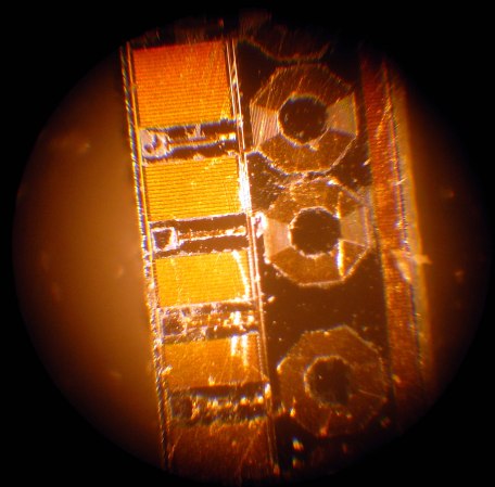
[Lindsay] followed [Ben Krasnow]’s video tutorial on how to decap chips, but replaced the nitric acid with concentrated sulphuric acid, which is a bit easier to obtain. The process involves heating the chip while applying an acid. Over time, the packaging material is dissolved leaving just the silicon. Sure enough, one of the three dies consisted of five coils that make up the isolation transformers. Each transformer has 15 windings, and the traces are only 4μm thick.
After the break, you can watch a time lapse video of the chip being eaten by hot acid. For further reading, Analog Devices has a paper on how iCoupler works [PDF warning].
[Thanks to Chris for the tip!]


You guys are making things way too complicated. There is no acid required to decapsulate chips.
1) Use a hot air gun (paint remover) to heat the chip and evaporate the binder until the package gets really brittle and only the filler remains This should be done outside as nasty fumes are generated.
2) Break chip apart.
This is true if you only need to take photos. The acid method is necessary if you want the chip to be functional after decapping though.
sooo just like in THIS very case (bond wires were damaged anyway)
For more techniques of decapping, see [siliconpr0n]
http://siliconpr0n.org/wiki/doku.php?id=decap:start
Nice video! The final conclusion about the inductor form may be true but can’t be the whole picture. The must be another inductor for it to couple to! If there was just an inductor there there would be no airgap separation! There must be another coik for it to couple to. MYbe on an internal metal layer?
@cjwoodall Re: ” must be another inductor for it to couple to”
The Analog devices PDF does show transformers as you describe them (one winding on top of the other) They also have an invertor and isolating transformer to transfer 5V as well as the data. A very cool device !
Yeah! Super cool stuff. I actually worked with some last summer for an interesting project. I found them super cool and I actually have some scribbles and circuits around to simulate the transmission mechanism they use on a 1:1 signal transformer and some 7400 logic. I was going to build and submit it for the 7400 logic competition, but that didn’t happen this year.
Maybe I will finish it up and do a write-up! Super cool tech.
Sorry about the typos in my last post, my phone hates me.
I think you mean 15 _turns_. 15 windings would be insane for something like this.
Also, is there another set of coils on the other side of the die or something? I’m a bit puzzled as to what they’re actually coupled to. I can see the data windings coupling horizontally, but what’s that power transformer doing?
The picture from Analog is probably from a module without power, there are 2 transformers for power and 3 transformers for data. There is some kind of feedback engineered into the data transformers, either an interrupt signal plus data and clock, or a synchronized clock and send plus receive data lines.
My guess at least.
you guys should make images before the jump link to the post, not the WP image media page or whatever
Interesting chip, but I wouldn’t trust 20um of polyimide to save my expensive computer from any high voltage on the USB port. The classic optocoupler or discrete ferrite method is probably much safer and if it fails, it fails towards ground (if ferrite core is grounded) and not directly into the USB port.
Can you elaborate a bit or propose design? I’d like to see USB isolator made from discrete components…
I would bee really interested to see your proposed design too.
Hi, thanks for the posting. Just noticed all the traffic to my site ;-)
Yes, there will be another set of windings underneath those that are visible. I tried to see how the bond wires were attached as I was etching it, but unfortunately it was very difficult with my crappy microscope, and I decided to just get the bare dies out and see what they were like.
A discrete optocoupler or isolator (e.g. magnetoresistive, http://www.nve.com) would certainly be possible, although bulkier. In fact, I’m running an FTDI serial chip after this at only 115200 baud, so another option might’ve been to isolate the serial lines, rather than the USB interface itself. However, in the end, a single USB isolator chip was simplest.