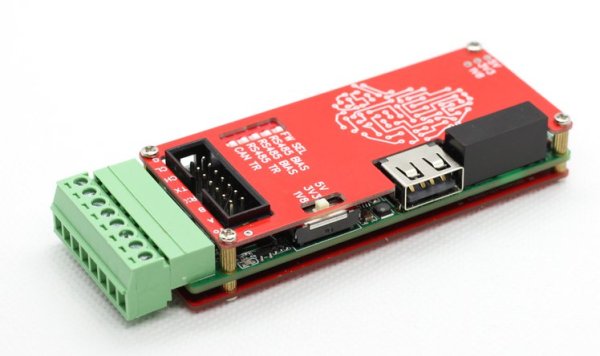
USB Power Isolator Keeps Smoke In

Anyone who’s done an electronics project knows the most important part of any good design is making sure to keep the magic smoke inside of all of the components. There are a lot of ways to make sure the smoke stays in there, but one of the most important is making sure that the power supply is isolated. If you’re using a USB port on a computer as your power source, though, it can be a little more complicated to isolate it from the computer.

The power supply is based around a small transformer with a set of diodes to act as a rectifier. Of course, while a transformer is great at isolating power supplies, it isn’t much good at DC. That’s what the ATtiny microcontroller is for. It handles the high-speed switching of the MOSFETs, which drive the transformer and handle some power regulation. There are two different power supplies created as part of this project as well — the first generates +5V much like a normal USB plug would have, and the other creates both +5V and -5V. It will be important not to mix these two up, or that tricky blue smoke may escape.

The project page goes into extensive details on the operation of the device, so if electrical theory is of interest, this will definitely be worth a read. Isolating a valuable computer from a prototype circuit is certainly important, but if you’re looking for a way to isolate a complete USB connection, look at this build which includes isolation for a USB to FTDI adapter.

Motor Controller Reverse Engineering Releases Smoke

It may have been designed for a sewing machine, but [Haris Andrianakis] found his imported DC brushed motor was more than up to the challenge of powering his mini lathe. Of course there’s always room for improvement, so he set out to reverse engineer the motor’s controller to implement a few tweaks he had in mind. Unfortunately, things took an unexpected turn when plugging his AVR programmer into the board’s ISP socket not only released the dreaded Magic Smoke, but actually tripped the breaker and plunged his bench into darkness.

Studying how the Hall-effect sensors in the motor are wired.

Upon closer inspection, it turned out the board has no isolation between the high voltage side and its digital logic. When [Haris] connected his computer to it via the programmer, the 330 VDC coming from the controller’s rectifier shorted through the USB bus and tripped the Earth-leakage circuit breaker (ELCB). The good news is that his computer survived the ordeal, and even the board itself seemed intact. But the shock must have been too much for the microcontroller he was attempting to interface with, as the controller no longer functioned.

Now fully committed, [Haris] started mapping out the rest of the controller section by section. In the write-up on his blog, he visually masks off the various areas of the PCB so readers have an easier time following along and understanding how the schematics relate to the physical board. It’s a nice touch, and a trick worth keeping in mind during your own reverse engineering adventures.

In the end, [Haris] seems to have a good handle on what the majority of the components are up to on the board. Which is good, since getting it working again now means replacing the MCU and writing new firmware from scratch. Or perhaps he’ll just take the lessons learned from this controller and spin up his own custom hardware. In either event, we’ll be keeping an eye out for his next post on the subject.

USB Adaptor Isolates Multiple Serial Interfaces

You need a Swiss Army knife of serial communications? Ollie is a compact isolated USB adaptor that provides USB, CAN bus, and two UARTs at logic, RS-232, and RS-485 signaling levels, as well as an isolated power supply.  [Slimelec] has managed to squeeze all this into a package the size of a harmonica.  We like the technique of making the enclosure from PCB material, complete with clearly labeled switch, LED and connector pinout names.

So far, only the compiled firmware is available for this project, but hardware files, and presumably the source code and documentation, are coming soon.

The central themes here are  isolation and flexibility. We can’t find the isolation voltage in the project specifications, but the CANable project on which this adaptor is based provides 2.5 kV galvanic isolation.  A single isolated USB interface is also provided over a standard Type A connector. The four-wire logic-level UART signals are available on a 2 x 7 box header, and are voltage selectable.  The RS-232, RS-485, and CAN signals are on an 8-pin pluggable screw terminal block, or you can use a DB9 connector with a pluggable adaptor board.

Whether you need a troubleshooting aid for field testing, are using CAN bus on your projects, or just want to isolate your expensive computer from sketchy prototype hardware, have a look at this project.

Stepper-Controlled Chop Saw Automates A Tedious Job

We’re not going to question why [Absorber Of Light] needs to cut a bazillion little fragments of aluminum stock. We assume his reasoning is sound, so all we’re interested in is the automated chop saw he built to make the job less tedious, and potentially less finger-choppy.

There are probably many ways to go about this job, but  [Absorber] leaves few clues as to why he chose this particular setup. Whatever the reason, the build looks like fun, with a long, stepper-driven threaded rod pushing a follower down a track to a standard chop saw. The aluminum stock rides in the track and gets pushed out a set amount before being lopped off cleanly as the running saw is lowered by a linear actuator. The cycle then repeats until the stock is gone.

An Arduino controls the stock-advance stepper in the usual way, but the control method for the linear actuator is somewhat unconventional. A second stepper motor has two cams offset by 180° on the shaft. The cams actuate four microswitches which are set up in an H-bridge configuration. The stepper swivels back and forth to run the linear actuator first in one direction then the other, with a neutral position in between. It’s an interesting approach using mechanical rather than the typical optical isolation. Check it out in action in the video below.

We’ll admit to some curiosity as to the use of the coupons this rig produces, so maybe we’ll get lucky with some details from [Absorber Of Light] in the comment section. After all, we knew exactly what the brass tubes being cut by the similar “Auto Mega Cut-O-Matic”  were being used for.

Continue reading “Stepper-Controlled Chop Saw Automates A Tedious Job”

Ask Hackaday: Is USB Robust Enough?

Earlier this month a single person pleaded guilty to taking down some computer labs at a college in New York. This was not done by hacking into them remotely, but by plugging a USB Killer in one machine at a time. This malicious act caused around $58,000 in damage to 66 machines, using a device designed to overload the data pins on the USB ports with high-voltage. Similar damage could have been done with a ball-peen hammer (albeit much less discreetly), and we’re not here to debate the merits of the USB Killer devices. If you destroy property you don’t own you should be held accountable.

But the event did bring an interesting question to mind. How robust are USB ports? The USB Killer — which we’ve covered off and on through the years —  is billed as a “surge testing” device and operates by injecting -200 volts DC on the data lines of the USB connection. Many USB ports are not protected against this and the result is permanent damage to the computer hardware. Is protection for these levels of abuse necessary or would it needlessly add cost to our machines?

A chip like the TPD4S014 has ESD protection on the data lines that is rated up to +/- 1500 volts, clamping to ground to dissipate the energy. It’s a solution that should protect against repeated spikes on the data lines, as well as short circuits on the power lines and over/undervoltage situations.

ADUM4160 Functional Diagram

The ADuM4160 is an interesting step up from this. It’s designed to provide isolation between a USB host and the device connected to it. Rather than relying on clamping, this chip implements isolation through air core transformers. Certainly this would be overkill to install in every product, but for those of use building and testing USB devices this would save you from “Oops, wrong USB cable” moments at the work bench.

Speaking of accidents at the bench, there is certainly a demand for USB isolation outside of what’s built into our computers. Earlier this year we saw a fantastic take on a properly-designed USB power strip. Among the goals were current limiting, undervoltage protection, and a proper power disconnect switch for each port. The very need to design your own reminds us that consumer manufacturers are often lazy in their USB design. “Use a USB hub” is bad advice for protection at the workbench since quality of design varies so wildly.

We would be interested in hearing from anyone who has insight on standards applying to equipment continuing to survive over current or over voltage events and remain functional. There are standards like UL-60950 that should apply to USB. But that standard includes language about failing safe for the operator, not necessarily remaining functional:

After abnormal operation or a single fault (see 1.4.14), the equipment shall remain safe for an OPERATOR in the meaning of this standard, but it is not required that the equipment should still be in full working order. It is permitted to use fusible links, THERMAL CUT-OUTS, overcurrent  protection devices and the like to provide adequate protection.

So, we’re here to ask you, the readers of Hackaday. Are our USB devices robust enough? Do you have a go-to USB protection chip, part, or other circuit you like to use? Have you ever accidentally killed a USB host device (if so, how)? Do you have special equipment that you depend on when developing projects involving USB? Let us know what you think in the comments below.

High Voltage Measurement Is Shockingly Safe

With the right equipment and training, it’s possible to safely work on energized power lines in the 500 kV range with bare hands. Most of us, though, don’t have the right equipment or training, and should take great care when working with any appreciable amount of voltage. If you want to safely measure even the voltages of the wiring in your house there’s still substantial danger, and you’ll want to take some precautions like using isolated amplifiers.

While there are other safe methods for measuring line voltage or protecting your oscilloscope, [Jason]’s isolated amplifier method uses high voltage capacitors to achieve isolation. The input is then digitized, sent across the capacitors, and then converted back to an analog signal on the other side. This project makes use of a chip from TI to provide the isolation, and [Jason] was able to build it on a perfboard while making many design considerations to ensure it’s as safe as possible, like encasing high voltage sections in epoxy and properly fusing the circuit.

[Jason] also discusses the limitations of this method of isolation on his site, and goes into a lot of technical details about the circuit as well. It probably wouldn’t get a UL certification, but the circuit performs well and even caught a local voltage sag while he was measuring the local power grid. If this method doesn’t meet all of your isolation needs, though, there are a lot of other ways to go about solving the problem.

A Sneak Peek At Anechoic Chamber Testing

[Mathieu Stephan] has something new in the works, and while he isn’t ready to take the wraps off of it yet, he was kind enough to document his experience putting the mysterious new gadget through its paces inside an anechoic chamber. Considering the majority of us will never get inside of one of these rooms, much less have the opportunity to test our own hardware in one, he figured it was the least he could do.

If you’re not familiar with an anechoic chamber, don’t feel bad. It’s not exactly the sort of thing you’ll have at the local makerspace. Put simply it’s a room designed to not only to remove echos on the inside, but also be completely isolated from the outside. But we aren’t just talking about sound deadening, the principle can also be adapted to work for electromagnetic waves. So not only is in the inside of the anechoic chamber audibly silent, it can also be radio silent.

This is important if you want to test the performance of things like antennas, as it allows you to remove outside interference. As [Mathieu] explains, both the receiver and transmitter can be placed in the chamber and connected to a vector network analyzer (VNA). The device is able to quantify how much energy is being transferred between the two devices, but the results will only be accurate if that’s the only thing the VNA sees on its input port.

[Mathieu] can’t reveal images of the hardware or the results of the analysis because that would give too much away at this point, but he does provide the cleverly edited video after the break as well as some generic information on antenna analysis and the type of results one receives from this sort of testing. Our very own [Jenny List] has a bit more information on the subject if you’d like to continue to live vicariously through the accounts of others. For the rest of us, we’ll just have to settle for some chicken wire and a wooden crate.

Continue reading “A Sneak Peek At Anechoic Chamber Testing”