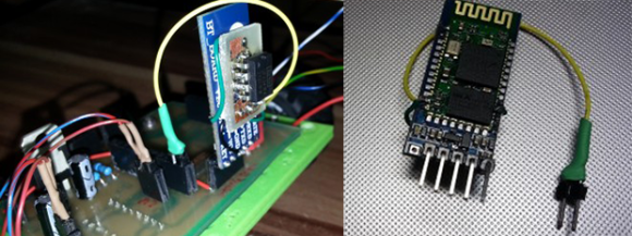
[Zenios] and [Raivis] are building a small balancing robot, and for communications to the outside world, they’re using a small, extremely cheap Bluetooth adapter. They figured uploading code to the microcontroller over Bluetooth would be a good idea, but their adapter, a cheap HC-06 module, had no way of resetting the microcontroller; it just provided Tx and Rx the serial port. They did notice a LED blinked when a device wasn’t connected to the adapter, so with a simple circuit they kludged a reset circuit where it wasn’t intended.
The small LED on the HC-06 module blinks when nothing is connected, and remains on when a connection is established. Figuring a new connection would be a good time to upload new code, the guys needed to design a circuit that would stay low when the LED was blinking, and switch to high when the LED was on.
A simple RC filter took care of the blinking LED, keeping the line low until a device connected. Bringing the logic level high when the LED stayed solid required digging through a part drawer, eventually finding an LM741 p differential amplifier.
After a few small changes to the bootloader, the guys had a reliable means of flashing new firmware without the need of programming adapters or wires draped over their workspace, all with a Bluetooth adapter that shouldn’t have this capability. Video below.


555 timer could also be used to basically change the pulse timing so it’d go low and stay low when the trigger’s pulsing and stay low for x time after last pulse to go back high and stay high.
With probability near 95% this module uses BlueCore chip from CSR. There are proprietary IDE named Bluelab exists for writing module firmware. Really, inside you will found GPL’ed GCC for some strange “XAP” architecture (without sources, of course, as big companies like to do with GPL’ed soft) and some ugly proprietary(?) IDE around it. AFAIK, XAP is some kind of virtual machine inside BlueCore chip, with access to high-level functions of Bluetooth protocol. The function of module completely depends on what is running in this virtual machine. BlueCore chips usually have serial port, few ADCs, some PWM, I2S port and USB device function and GPIO pins. BlueCore3 have complete audio circuit. Chips programmed over simple SPI bus. Ususally, cheap BT modules based on CSR chips have all signals wired to module pins, so there are no problem to use them in your project. You can make this module functioning as hands-free or Bluetooth-to-serial converter. Or, say, you can emulate Bluetooth mouse or USB dongle.
I succesfully build Bluetooth car lock system using cheap BT module with BC212 chip, reflashed with my own firmware. This module replaces PIC16F628 in some cheap KeeLOQ based car alarm system, but works over bluetooth channel in pair with my phone. Sources for BT module and Symbian phone can be found on my site.
So, for most projects with BT modules there are no need to build some electronics around module or connect it to another microprocessor just to have some additional function. The only thing you need is to write your own software for the module and flash it.
So, in this project there are no need to think out some strange solutions with led, just rewrite module firmware to use one unused GPIO pin as reset signal. And even more – probably it is possible to use module as the “brain” of the whole system.
While it seems very interesting to learn more about in internal vm of the bt modules it probably would take 100x as long to do that compared to just hooking up a simple pulse detector either with a 555 or a rc-network and a comparator….
It will take less time than learning Atmega programming. Especially, in case Atmega can be replaced with module.
Moreover, you can make BT-JTAG module, for example, for complete control over uC programming. Or add a watchdog function to the module to care about main system. Or use module ADC’s to get realtime wireless battery voltage and current monitoring independent from main uC.
I think this possibilities are good price for some time to learn very simple uC system. I spend less than an evening to make my module blink a LED with my own firmware. Next day I already was busy with field tests of new system on the car. AVR’s and PIC’s took much more time.
I think the point is to wirelessly update firmware of a micro controller at a reasonable price. Of course using one less chip is great, but we will loose the ability to update wireless.
So why not make a BT-JTAG module? Most of cheap BlueCore based modules can be programmed to do it. And reset line can be easily implemented too.
This cheap modules is over the 10 years on the market. They have very simple plain C Bluetooth stack API and programmed by very simple LPT-SPI converter (I just used few resistor voltage dividers to adjust LPT levels to 3.3V). But I never seen any hacks with changed module firmware. It’s very strange, because writing for and programming modules to make them do what you want is very easy.
Instead of direct use of module GPIO’s, ADC’s, etc, everybody put another uC next to stock programmed module (usually BT-Serial) and program that uC to make tasks easily can be done by module itself. It’s too strange, like, say, using some powerful PIC as serial-to-SPI converter and connecting AVR to SPI to just blink a LED by command over that overpowered serial-to-SPI converter.
I have a hard time finding any downloads for this BlueLab IDE except for as a part of a $3000 development kit.
When I was interested, I found BlueLab suite within 10 minutes using goolge. As I expected, it consists from GPL’ed tools slightly less than totally. Unfortunately, I didn’t find sources (as expected too) to build linux native build chain for XAP architecture, but nobody can’t stop me from using gcc, ar, ld, make and other utilities, even if they are distributed by some not so fair company as windows binaries for inadequate price. :)
@Stanson : From your slightly cryptic comment/reply I assume that what you found was a pirated copy at piratebay or some another torrrent site and not a proper download from the company….
GCC can’t be pirated, obviously.
Huh? So their IDE and Suite is only GCC and nothing else? Then it would be a very crappy IDE.
IDE is something written using Qt and Python and named xIDE. It’s really crappy. Really, it is an editor with poor syntax hiligthing and a tool to run ‘make’ command. Say, KDevelop is much better IDE. Really, xIDE itself is not necessary to write code, it’s easier to write makefile and build as usual.
The only “pirating” issue with CSR toolchain can be in BluCore “OS” “binary” itself, but there is simple workaround.
In short – module runs some kind of OS. This OS control RF and periferals and provides API for VM application which is define the function of module. VM application is stored in some kind of very simple filesystem on free from OS code space in flash. GCC builds this VM application from your source. It uses libraries with API calls. This very simple libraries (just wraps to OS syscalls) provided in sources without any license at all and builded with gcc on the first run. At the final stage, whole OS image merged with VM application and flashed into module. So, this OS image is the only necessary thing that can be named “pirated” with BlueLab distribution. But OS image can be easily downloaded from the module itself!
So, if you don’t want to “pirate” anything, just download OS image from your module and use it instead of image provided with BlueLab distribution.
There are also some proprietary tools to build final image and flash it over LPT-SPI, but they can be easily replaced by few-strings perl scripts and simple SPI-talking program.
Ok, sounds good enough. All of those steps really need to be described in a good step-by-step tutorial to make it easier for non-experts to get started without spending days pulling together and setting up/configuring all the required tools by trial and error.
The main problem is a lack of gcc and binutils sources for XAP architecture. Friend of mine, who have legal devkit at work, tried to get sources of all GPL parts of BlueLab suite from CSR, but completely failed.
JFYI – there are opensource assembler for XAP exists: https://gitorious.org/xap-tools
Tools for SPI flashing BlueCore modules (BlueFlash and BlueFlashCmd) freely available on CSR site in BlueSuite package. You have to register on CSR site to download it. BlueLab have this tools too.
Hey @Stanson, what you have achieved with the Bluetooth modules sounds awesome. Could you put together some screenshots or how-to doc that I could try to do what you have done? Cheers!
Second that
You can find some info, photo and sources here: http://translate.google.com/translate?sl=ru&tl=en&u=http%3A%2F%2Fwww.stanson.ch%2Findex.php%3Fpage%3Dproj%26proj%3DBT-CarLock
(sorry for google translation).
Only thing I failed to resolve is correct detection of moving to the car for automatic unlocking when I come closer straight to the car and not when I just pass near. This is because there are no good and correct way to detect distance using rssi and lq signals.
As for detailed howto – that’s not so easy, may be sometime…
Put two modules in your car, one on the front and one in the back and triangulate your approach angle based on distance difference? Or is the measurement not precise enough?
BT tranciever often change TxPower to keep the things working. You can have lowering RSSI and LQ when coming close. Shortly – you cant figure out distance beetween connected BT devices using accessible parameters like RSSI and LQ.
You can determine approximate distance or at least direction of travel with RSSI. You can configure TX power changing. If you had a proper CSR support contract…
One more link with some other project using bluecore module with some useful info:
http://byron76.blogspot.ru/
Very interesting! While following up on your links I found this other project also writing custom firmware for the CSR chips, which seems like a HaD-worthy project in itself:
http://pfalcon-oe.blogspot.com/2012/04/opensource-sensor-node-firmware-for.html
What makes it impossibly cheap? I found them for ~$6, surely I’m missing something?
Pretty sure the modules themselves also have RTS and CTS, the break-out boards just doesn’t “break them out”.
http://s27.postimg.org/vtbjta96b/Wireless_BTH_05_LRG.jpg
Ignore all the other connections, but take note of the serial connection pins in the upper left corner.
The pin-out is identical with those on the module.
So no need for all sorts of reprogramming when it all is there and available, you just need a level shifter circuit if your serial device doesn’t communicate on 3.3V level like the bluetooth modules do, otherwise it is all a matter of jumper wires.
I did the same thing without any external hardware reset, by modifying the bootloader (optiboot) and using some slight trickery in the application code.
http://forum.arduino.cc/index.php?topic=201169.0
Or you could just write a decent bootloader that doesn’t need a hardware reset
Erm…. what about the classical way of sending a special command through the serial port that tells the micro: dude, go to bootloader. And so the bootloader runs and can update the firmware.
Or if you really want reset…. just connect the reset pin to the RX through a low pass filter. Send a lot of 0x00 through the serial port and the voltage will finally drop and reset the chip.
lot (about 6 times!!) cheaper: http://ncrmnt.org/wp/2014/02/27/rf24boot-a-universal-over-the-air-bootloader-for-all-those-ucs/
would love to see that ported to arduino
Or you can do what the rest of us to with that BT module…. reach over and touch the reset button.
Been sending Arduino programming over that specific model of BT module for well over 3 months now.
I’ve used similar modules before (HC-05). If you pull the KEY pin high you can change a number of settings using AT commands (due to their price I used them for a simple wireless serial link).
unfortunately the HC-06 version’s config options seem quite limited in comparison:
http://www.linotux.ch/arduino/HC-0305_serial_module_AT_commamd_set_201104_revised.pdf <–HC-05
http://www.micro4you.com/files/ElecFreaks/Bluetooth%20HC-06.pdf <–HC-06
Here is how to resolve this issue with HC06: http://byron76.blogspot.ru/
Just flash HC05 firmware.
Or write your own :)
Nice, such a shame didn’t notice it before, this could have been much better, than what we did.
There’s an even easier way. Move one resistor, and add a diode to a pro mini then you can use a break signal for reset.
http://nerdralph.blogspot.ca/2014/02/zero-wire-serial-auto-reset-for-arduino.html
The HC-05 actually has a user-configurable logic pin that changes state when the Bluetooth connects that can be used for reset : http://makezine.com/projects/diy-arduino-bluetooth-programming-shield/