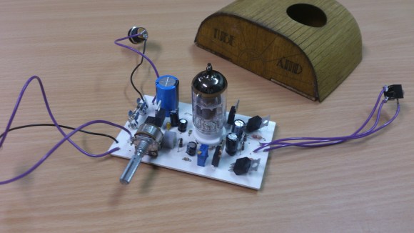
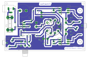
[Simon] wrote in to tell us about a headphone tube amp that he just built. It is based on schematics at diyaudioprojects.com that were actually featured on Hackaday in the past. [Simon’s] design adds an on board regulated power supply and a volume control for the input. Effort was made to keep the PCB single sided to facilitate making this at home.
 The 12AU7 is popular due to its ruggedness and tolerance for low operational voltages. This amp design uses a plate voltage of 12, although the 12AU7 can handle up to about 330. Since the 12AU7 is of the Twin Triode variety, one tube can be used to amplify both a left and right audio channel.
The case for the amplifier is laser cut plywood. The top piece is kerfed so that it can bend around the radii of the front and rear panels. The top also has a hole cut in it to allow the tube to peek out through.The pieces look nice but, unfortunately, he doesn’t show the case and amp in an assembled state.
If you’re interested in building one of these, [Simon] made all of the Eagle and Case files available. The total cost of the project was £25, about $43 US. To learn more about how tube amplifiers work, check out this Retrotechtacular from earlier in the year.


Transistor or FET amp with a tube gain stage. It quacks solid state!
Not just a FET. there’s also a 317 as a current source which adds even more solid-stateness
I’ve built one of the same design a while ago, in a proper metal box and everything. But the one thing that always bothered me was the noise floor… Maybe it was the headphones I was using (32 or 16 ohm), but the amplifier always had some white noise present, regardless of the power supply used. I even tried changing the constant current sink to no avail. Should probably dust it off and give it another spin in the future…
Did you use carbon film resistors or wire-wound? Carbon film resistors are much more prone to shot noise, so I’d probably start there.
I’ve been considering building one of these as well. ;)
The case is really cool!
It looks almost like the wood was repurposed from an old radio enclosure or something.
The cases were laser cut out of 1.5mm ply (if I’m recalling correctly)
They were designed by Simon to have that retro asthetic.
I’m sure we could pass on the design files for it if you wanted them.
They’re also linked on the page :)
Awesome. This is something, i would love to learn and tinker the sound of my headphones.
I still dont get the usecase of these devices O.o
May someone please enlight me? :(
Why would I want a tube headphone amp? Like for guitar playing with headphones?
tubes generate even order harmonics. its trendy to use tubes for voltage gain and the final stage being bipolar or mosfet for current gain.
as for the noise level comment, if you had noise you may need to check your gain level or gain structure (are you using gain then atten then gain in a later stage? stuff like that kills the total effective s/n).
as to the point of phones amps: some high-z phones need a decent amount of voltage swing to give a reasonable playback volume. also, most sources are bad at driving loads, they are pre-amp outs and not meant for driving phones. what most people need is a buffer, not really with much gain.
Because irony.
Too much silicon. why bother with the tube at that point.