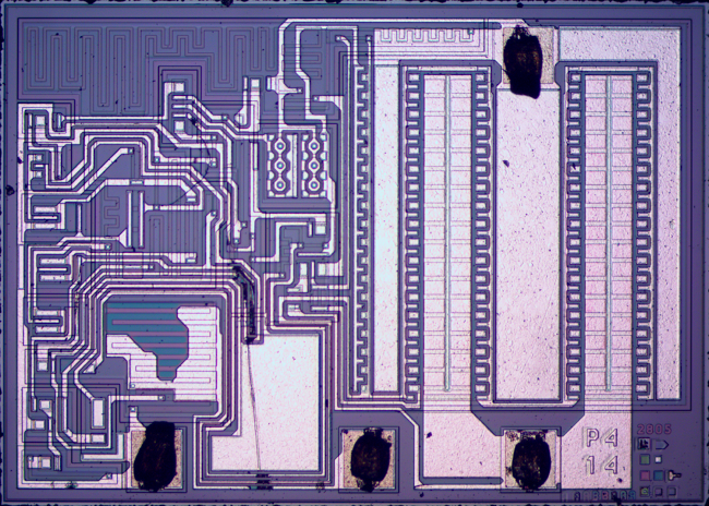
We’re quite sure that all hobbyists have used the 7805 voltage regulator at least once in their lives. They are a simple way to regulate 7V+ voltages to the 5V that some of our low power projects need. [Ken Shirriff] wrote an amazingly detailed article about its theory of operation and implementation in the silicon world.
As you may see in the picture above such a regulator is composed of very different elements: transistors, resistors, capacitors and diodes, all of them integrated in the die. [Ken] provides the necessary clues for us to recognize them and then explains how the 7805 can have a stable output even when its temperature changes. This is done by using a bandgap reference in which the difference between transistor base-emitter voltages for high and low current is used to counter the effects of temperature. As some elements looked a bit odd during [Ken]’s reverse engineering process, he finally concluded that what he purchased on Ebay may be a counterfeit (read this Reddit comment for another opinion).


I dont think it is counterfeit. The date code shows it is an old part from ’89 and that finish is very common on TO-3 packages. Thats surplus, old stock sitting in a warehouse never used.
Another increasingly likely possibility is that it is recovered e-scrap. A “recycled” recovered part, stripped from a scrap board, cleaned up to look like new and sold in one of the many far eastern markets. Parts rarely sit in a warehouse for 20+ years, particularly not parts that are as commonly used as this.
Did you really just use the words low-power, 5 V, and 7805 in the same sentence? That thing has a quiescent current of 5 mA; it blows through a 9 V battery in 5 days.
I did, so we wouldn’t see something in the lines of “try withdrawing 1A @5V from a 12V PSU with this 7805”
5ma is nothing. You can barely get an LED to glow on 5ma. So yeah 5ma is low power. Here’s an idea, if you want to run something for 5 days, or more, use something better than a 9V battery.
Lol.
Have you heard about those new-fangled superbright LEDs yet?
We even have white LEDs these days!
Do try to keep up, son.
(Say, shouldn’t you be out changing the world like the wolf you are, rather than posting here like the rest of the sheep? Baaaaaaaa.)
Ehm, no. Bigger battery capacity is not a good solution. Trust me, 5mA is a lot of loss power on battery running. My last low energy project run on 3x AA batteries which together have more power than usually used 9V type. DC/DC with low power consumption come pretty handy. IMHO 7805 is bad stereotype also like MAX232, in these days we have better solution.
I’m curious. What is the low power replacement for the MAX232?
MAX3232. Runs on 3V3 :)
(V batteries last over a year in a smoke detector.
While “low power” is a relative measure, burning 5ma in a linear voltage regulator that’s doing nothing doesn’t fit in to any definition of low power.
This is the sort of thing I am talking about… http://www.ibtimes.com/why-pentagon-finding-counterfeit-chinese-electronics-critical-military-equipment-701214
I didn’t look at your link, but this article is likely better
http://sound.westhost.com/counterfeit.htm
Elliott probably knows a bit more about electronics than the Pentagon does.
Is there any particular reason you are a douchebag or are ya just trollin?
you haven’t been around here very long, have you?
OK I just looked at the other article now. So now I’ve no doubt the article I linked is far better. Tell me, were you born as stupid as you are today, or have you been working at it your entire life?
Keep those sheep in line, dude.
Baaaaaa.
This has me thinking…
I wonder if some components could actually be more reliable if sourced used. Here’s my logic. There are two points in a component’s life that it is most likely to fail. It is most likely to fail in the begining of it’s life or after many years of use. (Assuming of course that it gets built into a well designed device with power levels in tolerance, etc…) Some components will always fail early on because of manufacturing defects.
If used components are properly tested then these early failures should be eliminated. So… could used components possible be more reliable than new ones?
Of course.. this assumes good testing, careful desoldering and handling. I’m not claiming that the actual ‘counterfeits’ found online where someone is trying to trick buyers can be trusted for any of those things. Also.. certain components like things which are higly sensitive to static discharge, temperature/mechanically delicate components and electrolytic capacitors also would probably be a bad idea to get used.
Excellent reverse engineering in Shiriff’s article. I particularly appreciated the explanation of the band gap reverence. Oddly, though, I could not find any mention of the numerous indications of overstress, from the large melted arc path above the compensation capacitor to the numerous melted-open stripes. The chip in the photo is a blown chip.
James, you’re the only person to notice (or at least mention) the damage to the chip. I tried too hard to clean off some specks of debris for the die photos and damaged the chip slightly. In particular I got a big scratch on the capacitor and damaged the metal layer in a couple places as you noticed. (Probably the bond wires made the scratches.) Annoyingly, I didn’t even manage to get rid of the dirt.
Ok, the stripes that I called melted-open could indeed have been mechanically damaged by whatever scratched the capacitor top plate. The open areas are all in a more or less straight line. It is usually hard to scratch all the way through the metallization.
I wish that I could have your article on hand when I was doing failure analyses on 7805 chips (about 15 years ago). It would have greatly added to my understanding.