Drop-In Switch Mode Regulators

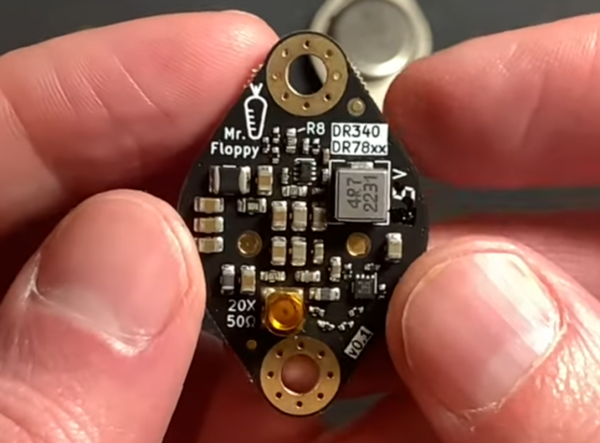
Perhaps the simplest way to regulate a DC voltage is using a voltage divider and/or an active device like a Zener diode. Besides simplicity, they have the additional advantage of not being particularly noisy, but with a major caveat: they are terribly inefficient. To solve this problem a switching regulator can be used instead, but that generally increases complexity and noise. With careful design, though, a switching regulator can be constructed to almost completely replicate a linear regulator like this drop-in TO3 replacement. (Google Translate from German)

While the replacement regulator was built by [Mr. Floppy], the units are being put to the test in the linked video below by [root42]. The major problem these solve compared to other switching regulators is the suppression of ripple, which is a high-frequency artifact that appears on the DC voltage. Reducing ripple in this situation involved designing low-inductance circuit traces on the PCB as well as implementing a number of EMI filters on both input and output. The final result is an efficient voltage supply for retrocomputers which has a ripple lower than their oscilloscopes can measure without special tools.

[root42] is not only testing these, but the linked video also has him using the modules to repair a Commodore 1541 which originally had the linear TO3 voltage regulators. It’s definitely a non-trivial task to build a switching power supply that meets the requirements of sensitive electronics like these. Switch mode power supplies aren’t new ideas, either, and surprisingly pre-date the first commercially-available transistor although modern ones like these are much less expensive to build.

Continue reading “Drop-In Switch Mode Regulators”

Printed Upgrades Improve Cheap Digital Microscope

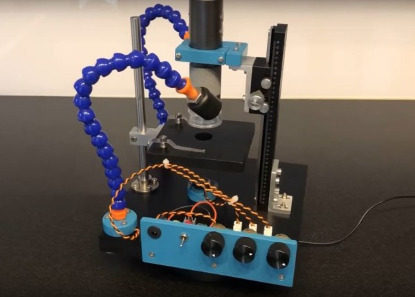
Digital microscopes used to be something that only labs or universities might have, but as image sensor technology has progressed, the prices have fallen to the point that any classroom or hobbyist can easily obtain a usable device. The only problem is that a lot of features and quality have been lost to make some of these digital microscopes more affordable. In an effort to add some of these creature comforts back into more inexpensive devices, [Marb’s lab] has created a special carriage for one of these microscopes.

The first addition to the microscope is improved lighting. To accomplish this, three LEDs were built into custom housings and wired to a purpose-built LED driver board coupled with a voltage regulator. Two of the LED housings were attached to the end of adjustable arms, allowing them to be pointed in whichever direction is needed. The third is situated directly below the microscope underneath the stage. These are all mounted to a large, sturdy PVC base which also holds an adjustable carriage for the microscope itself. This allows much more fine-tuning of the distance between the sample and the microscope than it otherwise would have had.

For just a few dollars and a little bit of effort, the usability of a device like this is greatly improved. If you want to take the opposite approach and really go all-out for your microscope, though, take a look at these microscopes used for PCB circuit construction and troubleshooting or even this electron microscope for viewing things at a much higher magnification than any optical system would allow.

Continue reading “Printed Upgrades Improve Cheap Digital Microscope”

MOSFET Heater Is Its Own Thermostat

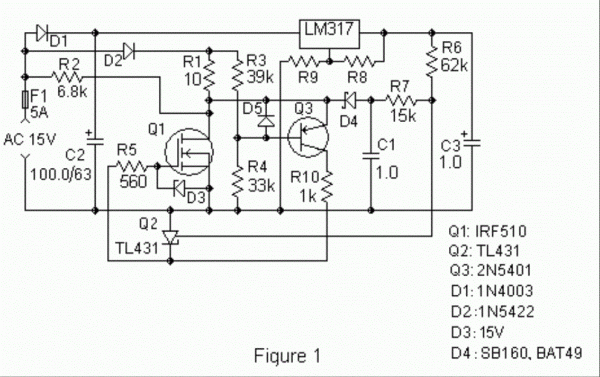
While we might all be quick to grab a microcontroller and an appropriate sensor to solve some problem, gather data about a system, or control another piece of technology, there are some downsides with this method. Software has a lot of failure modes, and relying on it without any backups or redundancy can lead to problems. Often, a much more reliable way to solve a simple problem is with hardware. This heating circuit, for example, uses a MOSFET as a heating element and as its own temperature control.

The function of the circuit relies on a parasitic diode formed within the transistor itself, inherent in its construction. This diode is found in most power MOSFETs and conducts from the source to the drain. The key is that it conducts at a rate proportional to its temperature, so if the circuit is fed with AC, during the negative half of the voltage cycle this diode can be probed and used as a thermostat. In this build, it is controlled by a set of resistors attached to a voltage regulator, which turn the heater on if it hasn’t reached its threshold temperature yet.

In theory, these resistors could be replaced with potentiometers to allow for adjustable heat for certain applications, with plastic cutting and welding, temperature control for small biological systems, or heating other circuits as target applications for this type of analog circuitry. For more analog circuit design inspiration, though, you’ll want to take a look at some classic pieces of electronics literature.

The 7805 Is Dead! Long Live The 7805!

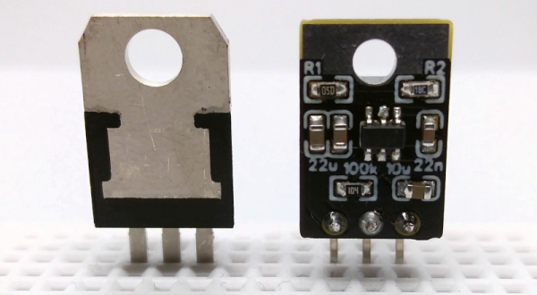
The 78XX series of regulators are very handy to use. If you need, say, a 5V regulator, you grab a 7805, add a capacitor for stability, and send in enough voltage for the regulator to work with. Cheap and easy. However, the part is not without its faults.

A stock 7805 can’t convert 5.1V to 5V. You need to have a good bit more voltage coming in. But the more voltage you put in, the more the part is going to dump out as heat. So running from 9V is going to be cooler than running from 24V. All that heat isn’t very energy efficient on batteries, either. [Stefan] wanted to do better, so he made a drop-in replacement for these venerable regulators some time ago. But he’s recently made the board layouts available so you can build your own replacement, too.

The device accepts 4.5 to 16V, and you can select the output voltage using two resistors. You can draw up to 2A out of the regulator, which is more than you can say for a stock 7805.

Continue reading “The 7805 Is Dead! Long Live The 7805!”

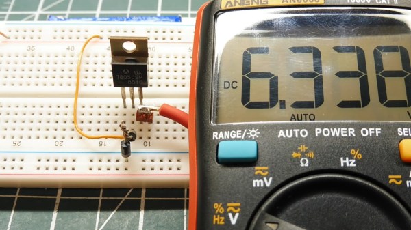
A 7805 Regulator puts out 6.3 Volts

Simple Electronic Hacks Inspire Doing More With Less

It’s late at night. The solder smoke keeps getting in your tired eyes, but your project is nearly done. The main circuit is powered by your 13.8 V bench supply, but part of the circuit needs 9 V. You dig into your stash to find your last LM7809 voltage regulator, but all you have is a bunch of LM7805’s. Are you done for the night? Not if you’ve watched [0033mer]’s Simple Electronic Circuit Hacks video! You know just what to do. The ground pin of a LM7805 connects to the cathode of a TL431 programmable Zener diode pulled from an old scrapped TV. The diode is referenced to a voltage divider, and voila! Your LM7805 is now putting out a steady 9 V.

How did [0033mer] become adept at doing more with less? As he explains in the video below, his primary source of parts in The Time Before The Internet was old TV’s that were beyond repair. Using N-Channel MOSFETs to switch AC, sensing temperature changes with signal diodes, and even replacing a 555 with a blinking LED are just a few of the hacks covered in the video below the break.

We especially appreciated the simple, to-the-point presentation that inspires us to keep on hacking in the truest sense: Doing more with less! If you enjoy a good diode hack like we do, you will likely appreciate learning Diode Basics by W2AEW, or a Diode Based Radiation Detector.

Thank you [DSM] for the tip! Be sure to submit your the cool things you come across to our Tips Line!

Continue reading “Simple Electronic Hacks Inspire Doing More With Less”

Dissecting A Mechanical Voltage Regulator

When the fuel gauge of his 1975 Triumph Spitfire started going off the scale, the collected knowledge of the Internet indicated that [smellsofbikes] needed to replace a faulty voltage regulator behind the dash. For most people, that would be the end of the story. But he, like everyone who’s reading this right now, really wanted to see what the inside of a 45 year old voltage regulator looked like.

After prying open the metal case, he discovered that not only is the regulator mechanical in nature, but there’s even a tiny screw that allows you to adjust the output voltage. Luckily for us, not only is [smellsofbikes] curious enough to open it up, but he’s also got the tools and knowledge to explain how it works in the video after the break.

Put simply, the heart of the regulator is a bimetallic strip with a coil of wire wrapped around it. When power from the battery is passed through the coil it acts as a heater, which makes the strip move up and break the connection to the adjustable contact. With the connection broken and the heating coil off the strip rapidly cools, and in doing so returns to its original position and reconnects the heater; thus starting the process over again.

These rapid voltage pulses average out to around 10 VDC, though [smellsofbikes] notes that you can’t actually measure the output voltage of the regulator with a meter because it moves around too much to get any sort of accurate reading. He also mentions a unique quirk of this technology: due to the force of gravity acting on the bimetallic strip, the output of the regulator will actually change depending on its mounting orientation.

On the oscilloscope, [smellsofbikes] is able to show us what the output actually looks like. As you might expect, it looks like a mess to 21st century eyes. But these were simpler times, and it should go without saying there aren’t any sensitive electronics in a sports car from 1975. Interestingly, he says he’s now replaced the mechanical assembly with a modern regulator chip. Here’s hoping we’re around long enough to see if he gets another 50 years out of it.

Continue reading “Dissecting A Mechanical Voltage Regulator”

An Adapter To Solve Your ESP-01 Breadboard Woes

The ESP-01 launched the ESP8266 revolution back in 2014, and while today you’re far more likely to see somebody use a later version of the chip in a Wemos or NodeMCU development board, there are still tasks the original chip is well suited for. Unfortunately, they can be tricky to use while prototyping because they aren’t very breadboard friendly, but this adapter developed by [Miguel Reis] can help.

Of course, the main issue is the somewhat unusual pinout of the ESP-01. Since it was designed as a daughter board to plug into another device, the header is too tight to fit into a breadboard. The adapter that [Miguel] has come up with widens that up to the point you can put it down the centerline of your breadboard and have plenty of real estate around it.

The second issue is that the ESP-01 is a 3.3 V device, which can be annoying if everything else in the circuit is running on 5 V. To get around this, the adapter includes an SPX3819 regulator and enough capacitors that the somewhat temperamental chip gets the steady low-voltage supply it needs to be happy.

[Miguel] has released the schematics and board files so you can spin up your own copy of the adapter, but they’re also available for around $3 USD from his Tindie store.