If you need to regulate your power input down to a reasonable voltage for a project, you reach for a switching regulator, or failing that, an inefficient linear regulator. What if you need to boost the voltage inside a project? It’s boost converter time, and Afrotechmods is here to show you how they work.
In its simplest form, a boost converter can be built from only an inductor, a diode, a capacitor, and a transistor. By switching the transistor on and off with varying duty cycles, energy is stored in the inductor, and then sent straight to the capacitor. Calculating the values for the duty cycle, frequency, inductor, and the other various parts of a boost converter means a whole bunch of math, but following the recommended layout in the datasheets for boost and switching converters is generally good enough.
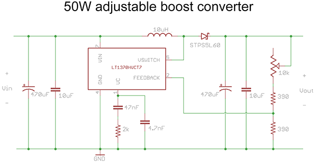
[Afroman]’s example circuit for this tutorial is a simple boost converter built around an LT1370 switching regulator. In addition to that there’s also a small regulator, diode, a few big caps and resistors, and a pot for the feedback pin. This is all you need to build a simple boost converter, and the pot tied to the feedback pin varies the duty cycle of the regulator, changing the output voltage.
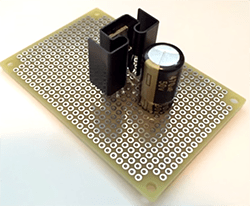
It’s an extremely efficient way to boost voltage, measured by [Afroman] at over 80%. It’s also exceptionally easy to build, with just a handful of parts soldered directly onto a piece of perfboard.
Video below.


Linear Tech is a fantastic company. Check out their free circuit simulator, LTSpice, downloadable from their website. My sales rep will mail me eval boards for any of their circuits, for free. It’s worth a try if you’re working on something that might go commercial. You can see how they’ve made me a happy customer :-)
Can we get stuff like this deleted. It has nothing significant to add to the article and is merely unsolicited advertising.
No. It’s a comment that does add something to the article. It says the manufacturer of a component in the build is a great company. That adds some amount of value to the comments here, and several times I’ve found components by reading hackaday comments.
You don’t get to see the actual unsolicited advertising that hits the comment spam queue, and you don’t want to. They don’t add to the article.
I like LTSpice. It has useful part information built in, and not LT ICs, I mean caps, mosfets, diodes, etc. that would be irritating to find all the SPICE parameters for.
You really want to find the proper Spice model for your MOSFET and BJT if you want accurate results.
I have seen a circuit that behave correctly in LTSpice, but not in the lab when I was using the built-in single line models. When I used the vendor’s (IRF) model of the MOSFET, it shows the same issue and agree with the result I got from the lab. After that, I know the LTSpice model was good enough and I spent my time debugging in the simulator. Being able to look at and “measure” waveforms freely in the circuit and tweaking circuit parameter saved me a lot of time than poking with scope and soldering/desoldering parts we happens to have in stock. It took me a couple of week to get the new design working in the simulator and it worked in the lab first time.
You must be a politician or practicing to become one. ;) At worst ka1axy’s comment is an unsolicited endorsement. The information could be useful to some in a general manner as well any any one wanting to experiment with the information provided by Afrotechmods.
I like the NCP1450 and NCP1402 boost converters for powering stuff from batteries. They work really well and are easy to use.
When your output voltage is lower than your input voltage it’s called a buck (switching) converter. Linear regulators really can’t compare to boosts because they always drop voltage. But that’s not all! There are so many topologies, very interesting hardware.
http version
http://www.youtube.com/watch?v=wJU7AJgERG8
The potentiometer on the upper part of the feedback divider is (very) bad design practice. If the connection were accidentally opened, the converter will push the output voltage higher and higher until something breaks down in a rather dramatic fashion. Best practice is to put the potentiometer between the last fixed resistor and ground.
That’s good feedback! (rimshot)
Will you make a new video for us? Perhaps say another few words about compensation circuits too? – Great channel, BTW!
It ain’t official until Afroman breaks it down for you.
Being [Afroman] and all, it don’t seem official without a rap:
The boost topology, makes the voltage get high
In it we use inductive collapse, to make the voltage get high
But you shouldn’t built it on perfboard, and I know why (yeah, why?)
Because of EMI, EMI, EMI.
seriously underrated post
you definitely don’t want to wire the pot where it is shown on that schematic, if there is a loose connection on wiper there is no feedback and the voltage will shoot up
Just tying the top of the pot onto the output line would add a safety backup for a loose wiper.
Wouldn’t it be easier to do the boost conversion in AC and then convert to DC when you’re up the level you desire? Doing it that way eliminates the need for the transistor and the inductor. I’m thinking a bridge (such as a Delon) circuit would serve nicely, or perhaps a doubled Greinacher (Cockcroft-Walton, if you wish). Perhaps I’m not accounting for some other factor here… I guess it depends on how much voltage gain you’re after.
I didn’t get the impression this was starting with AC at all. I figured it was a DC source like a battery. This circuit would’ve looked quite a bit different if making a flyback converter with AC input (which are also worthy), I think.
Voltage doublers are less efficient, larger, more expensive, etc than even a poorly designed switcher of equal power.
Lower the frequency, lower the efficiency, larger the size.
Voltage multipliers have bad/poor regulation, high output ripples and not flexible on the output voltage.
Afroman’s tutorials are AWESOME, the last time I checked (a year or two ago) he wasn’t making any new videos, so I’m glad he’s back.
I second that. It’s old now, but his review of the OWON SDS6062 was great!
Not a word about using LTSpice to help with the design?
Good spice simulator. Nice suite of tools provided by Linear Tech.
You missed the very first comment and its follow ups?
You don’t even need an external boost controller, you can use PWM from your MCU.
http://spritesmods.com/?art=ucboost&page=3
Isn’t that generally regarded as a bad idea, other than as a learning exercise? How long does it take the MCU to sample and adjust voltage? What happens if there is a bug in the code, particularly if the MCU is running something else as well?