At some point, the 3.6 V of a single lithium ion battery just won’t do, and you’ll absolutely want to stack LiIon cells in series. When you need high power, you’ve either got to increase voltage or current, and currents above say 10 A require significantly beefed up components. This is how you’re able to charge your laptop from your USB-C powerbank, for instance.
Or maybe you just need higher voltages, and don’t feel like using a step-up converter, which brings along with it some level of inefficiency. Whatever your reasons, it’s time to put some cells into series. Continue reading “Ultimate Power: Lithium-Ion Batteries In Series”→
[Trent M. Wyatt]’s CPUVolt library provides a fast way to measure voltage using no external components, and no I/O pin. It only applies to certain microcontrollers, but he provides example Arduino code showing how handy this can be for battery-powered projects.
The usual way to measure VCC is simple, but has shortcomings.
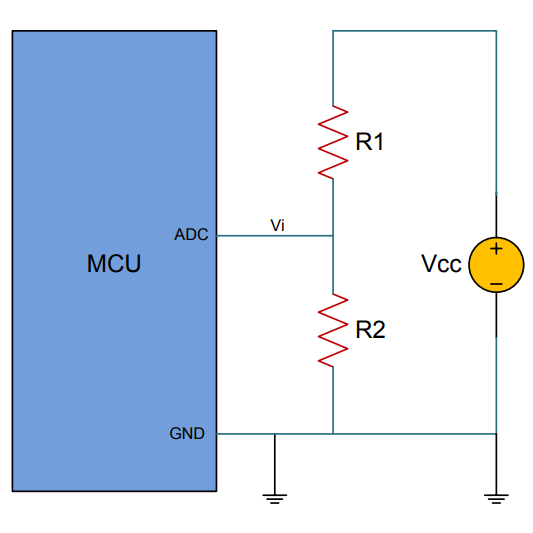
The classical way to measure a system’s voltage is to connect one of your MCU’s ADC pins to a voltage divider made from a couple resistors. A simple calculation yields a reading of the system’s voltage, but this approach has two disadvantages: one is that it constantly consumes power, and the other is that it ties up a pin that you might want to use for something else.
There are ways to mitigate these issues, but it would be best to avoid them entirely. Microchip application note 2447 describes a method of doing exactly that, and that’s precisely what [Trent]’s Arduino library implements.
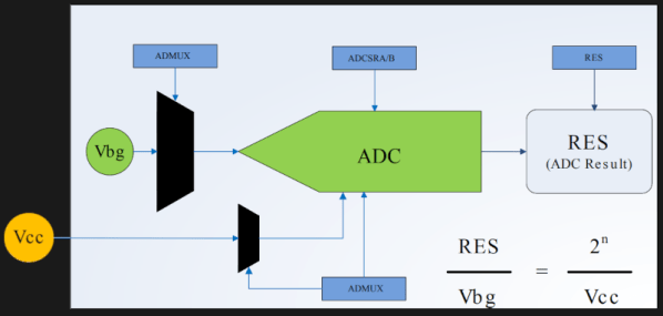
What happens in this method is one selects Vbg (a fixed internal voltage reference that is temperature-independent) as Vin, and selects Vcc as the ADC’s voltage reference. This is essentially backwards from how the ADC is normally used, but it requires no external hookup and is only a bit of calculation away from determining Vcc in millivolts. There is some non-linearity in the results, but for the purposes of measuring battery power in a system or deciding when to send a “low battery” signal, it’s an attractive solution.
Being an Arduino library, CPUVolt makes this idea very easy to use, but the concept and method is actually something we have seen before. If you’re interested in the low-level details, then check out our earlier coverage which goes into some detail on exactly what is going on, using an ATtiny84.
For one-off projects or prototyping, it’s not too hard to find a wall wart or power supply to send a few joules of energy from the wall outlet to your circuit. Most of these power supplies use a transformer to step down the voltage to a more usable level and also to provide some galvanic isolation to the low voltage circuit. But for circuits where weight, volume, or cost are a major concern, a transformer may be omitted in the circuit design in favor of some sort of transformerless power supply.
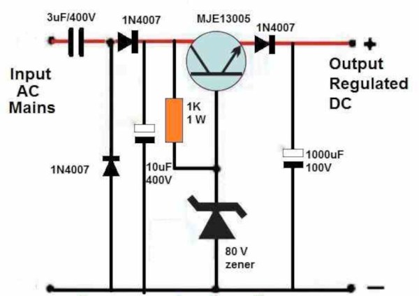
While power supplies with this design do have many advantages, some care needs to be taken with regard to safety. The guide outlines four designs of increasing complexity which first puts out a basic transformerless power supply, using a series capacitor to limit current. To bring the voltage to an acceptable level, a recognizable bridge rectifier is paired with a capacitor as well as a zener diode. The second circuit presented adds voltage stabilization using a transistor and 78XX regulator. From there, zero-crossing detection is added to limit inrush surge currents, and the final design uses the venerable 555 timer to build a switching power supply.
Although it is noted several times throughout the guide, we’ll still point out here that transformerless designs like these introduce several safety issues since a mistake or fault can lead to the circuit being exposed to the mains voltage. However, with proper care and design it’s possible to make use of these designs to build more effective power supplies that can be safe to use for powering whatever circuit might energy but might not require the cost or weight of a transformer. For more on the theory of these interesting circuits and a few examples of where they are often found, check out the shocking truth about transformerless power supplies.
As the old saying goes, there’s no such thing as a lock that can’t be picked. However, it seems like there are plenty of examples of car manufacturers that refuse to add these metaphorical locks to their cars at all — especially when it comes to securing the electronic systems of vehicles. Plenty of modern cars are essentially begging to be attacked as a result of such poor practices as unencrypted CAN busses and easily spoofed wireless keyfobs. But even if your car comes from a manufacturer that takes basic security precautions, you still might want to check out this project from the University of Michigan that is attempting to add another layer of security to cars.
The security system works like many others, by waiting for the user to input a code. The main innovation here is that the code is actually a series of voltage fluctuations that are caused by doing things like turning on the headlights or activating the windshield wipers. This is actually the secondary input method, though; there is also a control pad that can mimic these voltage fluctuations as well without having to perform obvious inputs to the vehicle’s electrical system. But, if the control pad isn’t available then turning on switches and lights to input the code is still available for the driver. The control unit for this device is hidden away, and disables things like the starter motor until it sees these voltage fluctuations.
One of the major selling points for a system like this is the fact that it doesn’t require anything more complicated than access to the vehicle’s 12 volt electrical system to function. While there are some flaws with the design, it’s an innovative approach to car security that, when paired with a common-sense approach to securing modern car technology, could add some valuable peace-of-mind to vehicle ownership in areas prone to car theft. It could even alleviate the problem of cars being stolen via their headlights.
Battery technology is the talk of the town right now, as it’s the main bottleneck holding up progress on many facets of renewable energy. There are other technologies available for energy storage, though, and while they might seem like drop-in replacements for batteries they can have some peculiar behaviors. Supercapacitors, for example, have a completely different set of requirements for charging compared to batteries, and behave in peculiar ways compared to batteries.
This project from [sciencedude1990] shows off some of the quirks of supercapacitors by showing one method of rapidly charging one. One of the most critical differences between batteries and supercapacitors is that supercapacitors’ charge state can be easily related to voltage, and they will discharge effectively all the way to zero volts without damage. This behavior has to be accounted for in the charging circuit. The charging circuit here uses an ATtiny13A and a MP18021 half-bridge gate driver to charge the capacitor, and also is programmed in a way that allows for three steps for charging the capacitor. This helps mitigate the its peculiar behavior compared to a battery, and also allows the 450 farad capacitor to charge from 0.7V to 2.8V in about three minutes.
If you haven’t used a supercapacitor like this in place of a lithium battery, it’s definitely worth trying out in some situations. Capacitors tolerate temperature extremes better than batteries, and provided you have good DC regulation can often provide power more reliably than batteries in some situations. You can also combine supercapacitors with batteries to get the benefits of both types of energy storage devices.
When you measure a voltage, how do you know that your measurement is correct? Because your multimeter says so, of course! But how can you trust your multimeter to give the right reading? Calibration of instruments is something we often trust blindly without really thinking about, but it’s not always an impossible task only for a high-end test lab. [Petteri Aimonen] had enough need for a calibrated current source to have designed his own, and he’s shared the resulting project for all to see.
The cost of a reference source goes up with the degree of accuracy required, and can stretch into the many millions of dollars if you are seeking the standards of a national metrology institute, but fortunately [Petteri]’s requirements were considerably more modest. 0.02% accuracy would suffice. An Analog Devices precision voltage reference driving a low-offset op-amp with a driver transistor supplies current to a 0.01% precision resistor, resulting in a reference current source fit for his needs. The reference is available in a range of voltages, his chosen 2.048 volts gave a 2.048 mA current sink with a 100 ohm resistor.
In a way it is a miracle of technology that the cheapest digital multimeter on the market can still have a surprisingly good level of calibration thanks to its on-chip bandgap voltage reference, but it never hurts to have a means to check your instruments. Some of us still rather like analogue multimeters, but beware — calibration at the cheaper end of that market can sometimes be lacking.
During my recent trip to Europe, I found out that converters were not as commonly sold as adapters, and for a good reason. The majority of the world receives 220-240 V single phase voltage at 50-60 Hz with the surprisingly small number of exceptions being Canada, Colombia, Japan, Taiwan, the United States, Venezuela, and several other nations in the Caribbean and Central America.
While the majority of countries have one defined plug type, several countries in Latin America, Africa, and Asia use a collection of incompatible plugs for different wall outlets, which requires a number of adapters depending on the region traveled.
Although there is a fair degree of standardization among most countries with regards to the voltage used for domestic appliances, what has caused the rift between the 220-240 V standard and the 100-127 V standards used in the remaining nations?