This article was prompted by a friend of mine asking for help on a board with an ESP32 heart. The board outputs 2.1 V instead of 3.3 V, and it doesn’t seem like incorrectly calculated feedback resistors are to blame – let’s take a look at the layout. Then, let’s also take a look at a recently sent in design review entry, based on an IC that looks perfect for all your portable Raspberry Pi needs!
What Could Have Gone Wrong?
Here’s the board in all its two-layer glory. This is the kind of board you can use to drive 5 V or 12 V Neopixel strips with a firmware like WLED – exactly the kind of gadget you’ll want to use for LED strip experiments! 3.3 V power is provided by a Texas Instruments TPS54308 IC, and it’s the one misfiring, so let’s take a look.
Last time, we went over switching regulator basics – why they’re wonderful, how do you find a switching regulator chip for your purpose, and how to easily pick an inductor for one. Your datasheet should also tell you about layout requirements. However, it might not, or you might want to deviate from them – let’s go more in-depth on what those requirements are about.
Appreciate The Feedback
There’s a few different switching regulator topologies. Depending on your regulator’s topology and how many components your chip contains, you might need some external components – maybe a Schottky diode, maybe a FET, or maybe even a FET pair. It’s often that the FET is built-in, and same goes for diodes, but with higher-current regulator (2 A to 3 A and above), it’s not uncommon to require an external one. For sizing up those, you’ll want to refer to the datasheet or existing boards.
Another thing is input and output capacitors – don’t skimp on those, because some regulators are seriously sensitive to the amount of capacitance they’re operating with. Furthermore, if you fail to consider things like capacitance dropping with voltage, you might make your regulator very unhappy – not that a linear regulator would be happy either, to be clear. We’ve covered an explainer on this recently – do check it out!
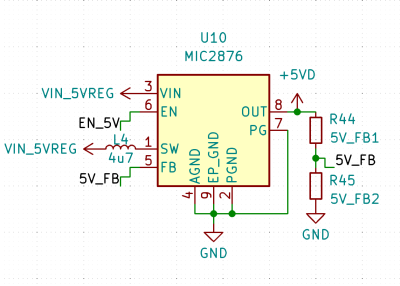
One thing you will likely need, is a feedback resistor divider – unless your switching regulator is pre-set for a certain voltage or is digitally controlled, you need to somehow point it to the right voltage, in an analog way. Quite a few switching regulators are set for a certain voltage output, but most of them aren’t, and they will want you to add a resistor divider to know what to output. There’s usually a formula for resistor divider calculation, so, pick a common resistor value, put it in as one of the resistors into the formula, get the other resistor value out of that formula, and see what’s the closest value you can actually buy. Don’t go below about 10 kΩ so that you don’t have unnecessary idle power consumption, but also don’t go too far above 100 kΩ to ensure good stability of the circuit. Continue reading “Switching Regulator Layout For Dummies”→
In the home computer market of the 1980s, there were several winners that are still household names four decades later: the Commodore 64, the Apple II and the Sinclair Spectrum, to name a few. But where there are winners, there are bound to be losers as well – the Mattel Aquarius being a good example. A price war between the bigger players, combined with a rather poor hardware design, meant that the Aquarius was discontinued just a few months after its introduction in 1983. However, this makes it exactly the type of obscure machine that [Leaded Solder] likes to tinker with, so he was happy to finally get his hands on a neat specimen listed on eBay. He wrote an interesting blog post detailing his efforts to connect this old beast to a modern TV.
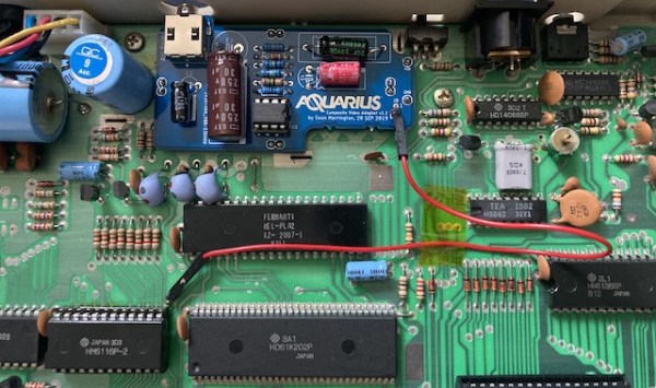
The main issue with the Aquarius is that it only has an RF video output, which results in a rather poor rendition of its already very limited graphics capabilities. Luckily, there is a fix available in the form of a composite A/V adapter that’s an almost plug-and-play upgrade. The only thing you need to do, as [Leaded Solder] illustrates in his blog post, is open up the computer, desolder the RF modulator and solder the A/V adapter in its place. Getting to that point was a bit tricky due to heavy EMI shields that were fixed in place with lots of solder, requiring liberal use of a desoldering iron. Continue reading “Adding Composite Video To The Mattel Aquarius”→
If you are an electronic engineer or received an education in electronics that went beyond the very basics, there is a good chance that you will be familiar with the Fairchild μA723. This chip designed by the legendary Bob Widlar and released in 1967 is a kit-of-parts for building all sorts of voltage regulators. Aside from being a very useful device, it may owe some of its long life to appearing as a teaching example in Paul Horowitz and Winfield Hill’s seminal text, The Art Of Electronics. It’s a favourite chip of mine, and I have written about it extensively both on these pages and elsewhere.
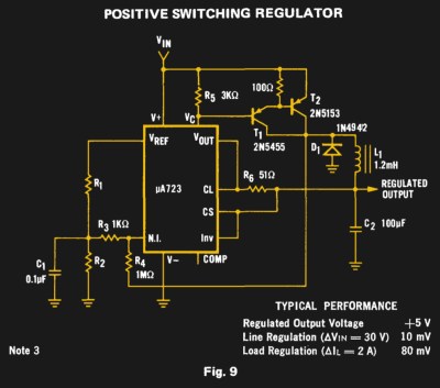
For all my experimenting with a μA723 over the decades there is one intriguing circuit on its data sheet that I have never had the opportunity to build. Figure 9 on the original Fairchild data sheet is a switching regulator, a buck converter using a pair of PNP transistors along with the diode and inductor you would expect. Its performance will almost certainly be eclipsed by a multitude of more recent dedicated converter chips, but it remains the one μA723 circuit I have never built. Clearly something must be done to rectify this situation.
Throwing a 5V regulator like the LM7805 at our projects can become habit forming, after all they’re dirt cheap and the circuit is about as basic as they come with only two external components, an input and output cap. As this is a good enough solution to most of our 5V circuits we can come into some issues if we aren’t paying attention. Linear regulators can only dissipate so much power in the form of heat before they need a heat sink and/or active cooling. Even if they can produce a cleaner output, in an embedded system, large power losses to heat are less than ideal to say the least.
[Daniel] needed an efficient solution to use in the place of an LM7805, after looking at the drop-in replacement switching solutions available on Adafruit’s website, he headed to DigiKey for a similar and less expensive part. [Daniel] collected some data and found the regulator to be 92% efficient with a 12V input, which is not quite the claimed 97% but a good solution nonetheless.
Restoring old gear often means replacing unavailable parts with modern equivalents. [Alex Eisenhut] needed to replace some old TO-3 voltage regulators and decided to make an authentic-looking switching power supply replacement. These three pin metal cans were very common, especially the LM340 5V regulator which was, of course, a linear regulator. Today, you are more likely to see a 7805 in a TO-220 case or something surface mount for a comparable linear regulator.
As you might expect, the board uses surface mount components. [Alex] used Mill Max machine pins to match the original regulator footprint and calls the regulator Ton3y. He plans to cover it up with a 3D printed lid, but it seems a shame to hide the fine PCB work.
In the pictures, you can see that the machine pins are a tight fit. [Alex] used a hammer to lightly tap them into place. Of course, the original TO-3 regulators were linear and would generate a lot of heat. The Ton3y, as you’d expect from a switching power supply, runs cool (according to the scientific measurement made with [Alex]’s pinky finger) and surely has a wider input voltage range and more output current capacity.
If you travel often, use your mobile devices a lot, or run questionable ROMs on your phone, you likely have an external USB battery pack. These handy devices let you give a phone, tablet, or USB powered air humidifier (yes, those exist) some extra juice.
[Pedro]’s PeriUSBoost is a DIY phone charging solution. It’s a switching regulator that can boost battery voltages up to the 5 volt USB standard. This is accomplished using the LTC3426, a DC/DC converter with a built in switching element. The IC is a tiny SOT-23 package, and requires a few external passives work.
One interesting detail of USB charging is the resistor configuration on the USB data lines. These tell the device how much current can be drawn from the charger. For this device, the resistors are chosen to set the charge current to 0.5 A.
While a 0.5 A charge current isn’t exactly fast, it does allow for charging off AA batteries. [Pedro]’s testing resulted in a fully charged phone off of two AA batteries, but they did get a bit toasty while powering the device. It might not be the best device to stick in your pocket, but it gets the job done.