Building a solar power installation isn’t as simple as buying a few panels, wiring them up to a battery, and putting an inverter in the mix. To get the most out of your pricey panels, you’ll want to look at something called Maximum Power Point tracking. Solar panels have an IV curve, and this changes with how much sunlight they’re getting. To get the most out of a set of cells, you need make sure you’re drawing the maximum amount of power out of your cells.
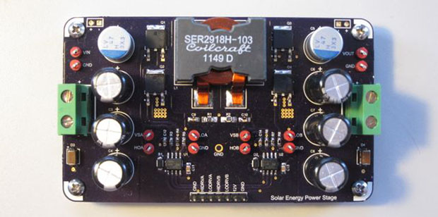
[Nathaniel]’s Solar Energy Generator does just that. It can handle up to 500 Watts, sucks power down from a bank of solar cells and spits that out to a battery. That’s not everything; the project also has a microcontroller for measuring and displaying all the pertinent info, and some terminals to plug in a few DC loads.
While the Solar Energy Generator is designed for off the grid applications, this could easily augment a home installation on the cheap. If you want more than 500 Watts or so, you’ll want to look at a larger controller, but for anything under that, [Nathan] has you covered.
Videos below.
 The project featured in this post is a quarterfinalist in The Hackaday Prize.


Could see this as being useful with smaller applications of Solar like Home boats, and off grid habitats. Combine with mesh and it would provide a great local power generating ‘Power houses.’ Instead of one big, like Linux lots of small.
ok, I can see where this is useful, having dabbled with solar + lifepo too. But mppt solar charge controllers are nothing new, if you would not DIY it the price would even be similar. So, meh.
500W in this size ? Not bad.
500W (fingers crossed) is my design goal. Each phase of the converter (it has two) will have FETs capable of dissipating less than 1W of power when switching 8A. All the power circuitry will be rated for at least 50V with some safety margin… who knows, may be able to do more than 500W. As I ramp up testing of my project over the next few months we will see.
How exactly is this project connected? I guess via the power in and outputs?
The project has terminal blocks to connect to batteries, panels and loads. But I am assuming you actually meant in terms of the contest – this is something I hope to work on soon – I want to create a set of I2C and SCI commands that can be used to access information from the generator. That way you can hook other peripherals up too it and allow them to make intelligent decisions with their power usage based on the available energy.
Nice work on the electronics.
I’m not so sure of the practical value of MPPT. I think the potential value is in battery management systems and not MPPT. If the MPPT can be added on for free, then OK.
Here’s why:
Individual solar cells are cheap now – 40-50c/W according to Digitimes and SolarBuzz. Full modules are available in small quantities for under $1/W. So for a 500W system, the panels are going to cost ~$500.
Average daily solar insolation in the most populated parts of the populated word works out to ~3kWh/kW, so on an average day a 500W system would provide 1.5kWh of power.
To store that power you would need 150 18650 lithium batteries @10Wh ea, and a cost of $5ea, for a total of $750.
For many of the days of the year, there will be more sun than the system can store, so MPPT will provide no benefit on those days.
If the 18650 cells are charged to 4.2v, you can expect ~500 cycles. Charging to 4.0V reduces the stress on the cells, and should increase the life to ~2000 cycles.
Given the high cost of replacing cells, a good BMS will have a payback in 1-2yrs. If the design is only to get maximum power out of the cells through MPPT, then the payback is questionable.
Using batteries to store solar power is a very small niche. Grid-tie is where the best economics exist. An efficient and inexpensive grid tie inverter would be much more useful than a MPPT battery-charger.
An efficient and inexpensive grid tie inverter may also be considered to be nearly useless. In the USA and the EU — IE almost the entire readership of this website, there are strict regulations and penalties involving connecting generating equipment to the power grid. UL and CE approval costs a lot of money, and while it’s not a problem for a major manufacturer to shell out hundreds of thousands of dollars a year (EVERY YEAR) to keep their product approved, it’s a pain for the little guy.
I guess you could always get an approved net metering setup installed using a very small legal grid tie inverter, then after the inspector leaves, hook up your giant homebrew unit and hope noone gets killed.
Also “I’m not so sure of the practical value of MPPT. ” …… I think that you meant to say ‘I’m not so sure of the practical value of MPPT—– FOR ME AND MY OWN USES’
Indeed, for offgrid systems the worst case is far more important then the average performance. Whether it’s cloudy days, low voltage from a half empty battery, reduced transition losses, or just being able to reuse an existing buried wire with more panels due to having the PVs at ~2x the battery voltage, the performance wins just keep adding up for off-grid users.
Just to point out, reoccurring UL and CE cost are not hundreds of thousands a year. More like ten thousand. Still substantial, yes, but a cost of doing business if you wish to sell products. Initial cost of compliance however can be $50k quite easily.
How about low voltage grid tie inverters that interface via a UL listed transformer assembly? Then the inverter itself would be low voltage and not need UL listing. I suppose the real challenge is to find a cheap UL listed transformer assembly that gets good efficiency and low standby losses.
I think you’re making some assumptions about usage patterns. Some folks always need more than their system can supply. Or meticulously plan their usage so there is never any wasted production. In either case the MPPT is always providing a benefit.
One could argue that such folks would be better served by adding more solar panels. But what if you don’t have a suitable place to put them? Or it’s a system designed to be small and portable? Payback period isn’t always the only consideration.
And 150x 18650 lithium batteries? Perhaps that was just for the sake of a convenient example, but otherwise that’s a poor choice. There are lithium cells with higher capacity per cell, lower cost per Ah, and longer lifetimes. That’s assuming you go with lithium at all, lead acid is probably still more economical.
I would agree that MPPT is not always useful – in a system where the battery voltage is closely matched to the panel voltage you may only be looking at say a 10% loss vs an MPPT. But in many cases those gains in power gain with MPPT can be up to 20-30%. Additionally, the DC-DC allows you to use very mismatched voltages between panel and battery have great gains that a traditional system that connects the battery directly to the panel does not. If you have a 12V lead acid with panel whose VMP is around 28V, you are throwing almost half the power away if you connect the panel and battery directly. The DC-DC give you to throw any panel and any battery on the converter and still achieve good results.
I see this project leader chooses not to have emails direct as the email given on his blog as an image only does not work anyhow . That ticks me off to start.
I am inquisitive about charging LiPo batteries as each must be charged separately to around 4V so how will he manage that if he uses say a 40Volt battery pack?
Also my experience with Dc-Dc converters attached to solar panels is very little comes out the battery end and most is consumed in the converter as heat . I tried an 80 Volt panel to 12 Volt battery and lost 80% in the converter . never understood why that was so high ?
I also tried it to a 24Volt lead acid battery pack with about the same losses ?
This is in principle exactly what this converter is used for – to avoid the losses of a linear (shunt-) regulator. That way, the battery voltage does not need to be as exactly matched to the panel – although a 4V battery pack would need excessively high currents to be charged. 80V input is likely too much for this design – but you could rewire your panels in parellel.
First the panel puts out 80 V so that’s what creates my problem .Second Its the DC-DC that’s losing the power on mine . Is yours somehow different to what I am using? I have DC-DC VOLTAGE REDUCER CONVERTER FROM 84V-36V (30V-110V) T… (370937908887) a bit like this
http://www.ebay.com.au/itm/DC-DC-3-35V-to-3-5-35V-Voltage-Step-Up-Boost-Converter-Module-w-Voltmeter-/300931951134?pt=LH_DefaultDomain_15&hash=item4610f12a1e
Ty Tower wrote:
> I have DC-DC VOLTAGE REDUCER CONVERTER
That might be a problem, you cannot use an unmodified, run-off-the-mill DC/DC-converter connected to the input of a normal solar shunt-type charge regulator.
That is because the shunt regulator expects a current source with high internal resistance, which is the characteristic of a solar panel. Most standard DC/DC converters have a fixed output voltage instead, and that means a low internal resistance. In other words, that means trouble.
If you definitely must use a solar panel with such a high output voltage, you might have to look further for a suitable MPPT charge regulator in order to use in in an off-grid setup.
As much as I like Coilcraft inductors, they can get quite expensive…
Great small design (if it works..)
MPP regulators are especially useful when using 12V lead/acid batteries with standard 60-cell panels which have typical MPP voltages of 25 to 30 volts.
With a cheaper shunt regulator, you would waste at least half the output power.
A somewhat useful extra for this project would be a fuse socket for the battery output added to the PCB.
Although a fuse in close proximity to the battery is the way to go to prevent fires in case of a short circuit anywhere down the line to the MPP regulator, I see people who forget about that. Or who mount the MPP regulator very close to the battery. (Generally a good idea)
Yeah im on the fence about where to put fuses. I was going to use put sockets for the mini automotive fuses next to the terminals, but may just end up being lazy and recommending that inline fuses be used.
I am more interested in knowing how much RF this thing emits.
Why, do you want to make a radio? If you’re worried about it, wrap it in a Faraday cage.
I did a similar project for my capstone course for my B.Eng. http://capstonefyp.wordpress.com/
Ours was capable of about 300W, I couldn’t test it beyond that. It’s actually uncanny how similar our board layouts (and the topology) are.
One word of advice, make sure you can measure current flow out of the battery (into the converter). I never took this into account, and ended up having a runaway condition where it thought there was 0 current flow and kept increasing the duty, when in actuality there was current flowing from the battery into DC-DC converter. We used current shunt resistors and op-amps. If I did it again I’d use hall effect sensors. I was worried about the power loss in the hall effect sensors (their internal resistance was much higher than our 3 parallel 5 milliohm resistors). For the 0.5% loss in efficiency vs not being able to measure bi-directional current flow, I’d go with the loss in efficiency with what I know now. Don’t underestimate the losses in your MOSFETs (to me they look undersized for 500W with only a PCB as the thermal plane).
(for reference our MPP was around 8.9A and 35V)
Good luck!