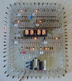
This is an oldie, but oh, man is this ever good. It’s a Nixie clock made without a microcontroller. In fact, there aren’t any logic chips in this circuit, either. As far as we can tell, the logic in this clock is made with resistors, diodes, caps, and neon tubes.
The design of this is covered in the creator’s webpage. This clock was inspired by a few circuits found in a 1967 book Electronic Counting Circuits by J.B. Dance. The theory of these circuits rely on the different voltages required to light a neon lamp (the striking voltage) versus the voltage required to stay lit (the maintaining voltage). If you’re exceptionally clever with some diodes and resistors, you can create a counting circuit with these lamps, and since it’s pretty easy to get the mains frequency, a neon logic clock starts looking like a relatively easy project.
This clock, like a lot of the author’s other work, is built dead bug style, and everything looks phenomenal. It looks like this clock is mounted to a plastic plate; a good thing, because something of this size would be very, very fragile.
Video below, thanks [jp] for sending this one in.


There were a few neon bulb logic projects that showed up in the hobbyist magazines back in the day. While they were neat, the need to buy and test so many bulbs to gather a set with parameters close enough to assure the circuit would work properly was beyond the means of most.
Doesn’t the mains frequency vary from time to time and from place to place enough to matter for accuracy purposes?
It does vary. It is especially bad in Britain because people insist on boiling water at the exact same time every day, causing a near-critical frequency dip.
However the National Grid regulate the frequency so that there are always the same number of cycles in a 24 hour period. Synchronous clocks as a result are generally more accurate than quartz controlled ones. I’ve got a couple of 1920s Ferranti mains powered clocks that keep way better time than any of the battery powered clocks in the house.
That explains why my mains frequency regulated Nixie Clock is so damned accurate.
There are several proposals to remove the requirement to “fix” the number of cycles in 24 hours. This will blow away all synchronous clocks. Say goodbye to them. You could, however, build a very accurate 60 Hz (in the US) oscillator and run it into a very stable audio amplifier, like a Crown D-60 to D-70. Run its output into an (illegally) wired in reverse 240 Volt to 120 Volt step-down transformer to make it a step up transformer. Use the volume control to set the Voltage at 210 Volts (in the USA).
We used to do this in radio in the 60s and 70s to be able to control the speed of turntables which used synchronous motors in order to control the speed by varying the frequency of the oscillator.
Ch00f had a good go at trying to work this out when testing his TTL clock. His findings show that although the frequency seems to drift a bit during peak-use hours, the utilities tend to counter for this during off-peak hours. A couple day test showed an average of a couple seconds of drift with a max of 7 but ended with a ‘more testing needed’ due to space.
http://ch00ftech.com/2012/07/24/are-you-sure-about-that-60hz/
Also, this;
http://leapsecond.com/pages/mains/
They could’ve just asked their utility.
They do compensate for drift in the long term.
Something I believe they’re trying to get rid of now.
The mains frequencies in Europe and North America are monitored and adjusted periodically to keep AC clocks’ accumulated error low over time.
http://en.wikipedia.org/wiki/Utility_frequency#Long-term_stability_and_clock_synchronization
The frequency is deliberately changed – sped up or slowed down – to average out errors.
Historically, the frequency was increased during non-peak hours such that the total number of cycles each day remained constant. Thus while a clock might speed up and slow down throughout the day, it would remain accurate over the long term.
However, many grids are in the process of eliminating the adjustment procedure, so depending on where you live mains-frequency-based clocks may no longer maintain the correct time over the long term.
This is very similar to a Nixie/Neon counter clock project that was made available several years ago from the Nuts&Volts magazine store and is still at http://www.nixieneon.com. However, that one does use a microcontroller for some limited functions, although the counting is I believe still purely analog through successive neon divider rings.
VERY COOL! Clocks are awesome!
Balls to da walls
thats beyond awesome….some hardcore hackery if i’d ever seen it!!!
I wonder if the operation is as flakey as some neon bulb things I’ve built — neon bulbs change their ignite voltage with time, they change with ambient light, the probably change with temperature. All in all I think it’s very difficult to make something like this that’s reliable enough to work day in and day out for years.
I’m not sure that’s really the point.
It’s too bad the original NE-96 bulbs aren’t available, they had a radioactive source in them that would allow them to operate properly in the dark.
Would attaching a piece of uranium ore or other easyish-to-get radiation source (penetrating enough to go through the glass) be helpful?
Uranium emits mostly Alpha, it would never get through the glass.
The cited link/inspiration in the video leads to a neon-clock where the guy uses light-dependent-resistors to try to compensate for the variable ignition voltage issue.
Even that didn’t totally solve it, so he ended up pointing some blue LEDs at the neons, which he claims works. Plus, looks cool.
But this version is all-neon, which gets extra cool points by me.
Lovely!
I am not sure if a radiation source would be useful in this case – the decay rate would likely be too small to cause any useful ionization during the small fraction of the 20 ms (for 50Hz operation) or 16,7 ms (60Hz) intervals that is available as ignition time for the first stage of the neon bulb counter.
I guess that a sufficiently high voltage spike is sufficient for reliable ignition even in a dark environment.
I just noticed that the lamps are not triggered by a high-voltage spike but rather turned off by a negative pulse. The problem with the limited decay rate of radioactive ionization likely still aplies.
But as the author of this project writes, changing the resistor values is very plausible to work. Because of the fold-back characteristic (negative internal resistance area) of the neon plasma lamps, an increased lamp current lowers the maintaining voltage, increasing the difference between maintaining and ignition voltage.
The circuit designer’s build was on hackaday in 2010:
http://hackaday.com/2010/01/13/neon-lamp-and-other-crazy-clocks/
There are a few videos of some great builds on YouTube, though this one is probably the best.
I like the fact that the actual operational circuits are part of the aesthetic appeal, function as art.