One of [aepharta]’s ‘before I die’ projects is a homebrew computer. Not just any computer, mind you, but a fabulous Z80 machine, complete with video out. HDMI and DisplayPort would require far too much of this tiny, 80s-era computer, and it’s getting hard to buy a composite monitor. This meant it was time to build a VGA video card from some parts salvaged from old equipment.
When it comes to ancient computers, VGA has fairly demanding requirements; the slowest standard pixel clock is 25.175 MHz, an order of magnitude faster than the CPU clock in early 80s computers. Memory is also an issue, with a 640×480, 4-color image requiring 153600 bytes, or about a quarter of the 640k ‘that should be enough for anybody.’
To cut down on the memory requirements and make everything a nice round in base-2 numbers, [aepharta] decided on a resolution of 512×384. This means about 100k of memory would be required when using 16 colors, and only about 24 kB for monochrome.
The circuit was built from some old programmable logic ICs pulled from a Cisco router. The circuit could have been built from discrete logic chips, but this was much, much simpler. Wiring everything up, [aepharta] got the timing right and was eventually able to put an image on a screen.
After a few minutes, though, the image started wobbling. [aepharta] put his finger on one of the GALs and noticed it was exceptionally hot. A heatsink stopped the wobbling for a few minutes, and a fan stopped it completely. Yes, it’s a 1980s-era graphics card that requires a fan. The card draws about 3W, or about two percent of a modern, high-end graphics card.


Very nice. Reminds me of Steve Chamberlin’s BMOW (I believe he also used GALs in the video circuit). I’d double check the wiring on that one GAL though.
Wiring check might be worthwhile. It looks like unused input pins are left floating. That’s generally not good practice with CMOS, as the input structures have high enough impedance that they tend to pick up stray EMI and needlessly toggle their input state, consuming a bit of extra current in the process. In some cases you can get high frequency self-oscillation, which draws more current. I once found a single floating and self-oscillating pin was wasting 5mA. Multiply by a large number of floating pins and it can add up to a significant amount.
I’m not familiar with any GALs specifically, so I looked up the datasheet on the 22V10. It says there are internal active pull-ups on all I/O pins. Yet still makes the recommendation that all unused pins, including pins set for output and tri-stated, be tied to VCC, GND, or some actively driven pin, to improve noise immunity and reduce Icc. That may merely be a “cover your arse against worst-case scenarios” type of statement on Lattice’s part. But I’d still try grounding unused pins, at least on the hottest chip, and see if it makes a difference. When I get complacent and trust that things will work as expected rather than verifying, too often I get bitten in the arse later.
Even if ground the pins do not affect the I/O pad current, it would help cooling the chip as you are improving the thermal path to a solid ground plane (hopefully you are using one).
Very, very cool! Thumbs up! :-)
A more modern CPLD would be able to run ice cold doing the same job.
Agreed. Most people are shocked when they look at how much current is drawn by GALs. It’s caused me to reconsider using them in a large number of situations, and they’re just sitting there pleading “use me! use me!”
Also more likely to have a GAL programmer on hand say vs a JTAG programmer for CPLD/FPGA. Once you guesstimate the size with margin and I/O requirement, you could make the PCB layout and then develop the code.
I did design and made a GAL programmer back in school day from the programming spec. I wrote a letter to NS and they mailed me me a hard copy. Couldn’t get one from AMD at all for their PALCE line.
THAT is fantastic! I never had the privilege of living in that era of computer technology, but it is awesome to see stuff built on retro tech! I have a TRS80 Model 4P lying around so I might just have to design a graphics card for that…
Retrocomputing is awesome, but you really didn’t miss much by not living through the computer revolution.
“but you really didn’t miss much by not living through the computer revolution.”
That created a lot of good jobs, essentially all of which are full now. So there’s that.
>640×480, 4-color image requiring 153600 bytes
4 Bit color
very cool project
640KB of RAM was enough for everybody in an era when the common mass-storage device was a 140 – 360 KB floppy, and software in general was designed to run with the 64 KB limitation of 8 bit machines.
Heck, imagine if today you could have 2 Terabytes of RAM in a common PC.
Hate to see that BIOS memory self test. :P Also ECC would be highly recommended.
Maybe not in common PCs, but you can. I know of at least one motherboard that can take 6TB of RAM (for 4 CPUs): http://www.supermicro.nl/products/motherboard/Xeon/C600/X10QBI.cfm
And that’s still DDR3, soon the new bigger DDR4 modules will push the limit a bit higher again
Yes, and you could own a Cray1 in 1981 too, if you were rich enough.
that has a limit of “only” 3TB.
Cornell’s lecture series on FPGAs taught me that all RAM isn’t equal. The bestest, fastest, most radical sort of RAM out there is dual-ported synchronous, and you might have heard of it as ‘VRAM’. The V stands for video, and reportedly non-VGA LCD panels don’t need it.
The densities are rather bad though. It’s fast but you don’t get a lot of it. If you have 1MB, you’re lucky.
Its measure of fastness is the fact that you can write to it and read from it at the same time. – I wonder where this fits into the Turing completeness saga; it seems so radical.
You can also use two separate RAM banks. Write to one, and read from the other, and then switch at the end of the frame. Cheaper than dual ported RAM.
Oooh… Nice trick. That is of course how you’re supposed to use dual-channe DRAM. :D
Run the memory (old DRAM) at 2X speed + flop/latch to allow the 2 ports (e.g. in Amiga CPU/Graphic) access at 180 clock phase.
I think I see the pattern of interleaving.
I wonder if there is a hardware design which does throuput when the read and write try to access the same bit at the same time.
If you are interleaving, there is no such case as writing to the same address at the same time (cycle) as it implies alternating access. So you either the read off the stale data or the new one.
I would assume that a real dual port memory with separate read and write channels would have flow through data when you are access the same address. There are real dual port memory where both ports have R/W from both side. You have to read the fine prints to find out when with 2 writes or 1 read/write etc.
Technically AMD EPYC CPUs can address 4TB of physical memory in a dual socket config half that in single socket… for a paltry $120-140k for the ram I’m sure there are actually companies out there that have actually bought that configuration 128GBx32
You can still buy “LED” TV with analog input e.g. Composite video and VGA. Not being able to find something with VGA inputs will be the next problem one of these days.
There are lower power versions of GAL chips, some are quarter power if you look hard enough. It was funny that I managed toreplace a PAL chip by rewiring a 74F part that consume 1/5 the power. 74F parts are built for speeds and exactly known to be lower power.
I would assume that just by swapping & reprogramming the GAL with the faster speed grades, he could do without cooling. The part can handle the heat as they are meant to, but heat degrades the timing.
Most modern TV’s have composite video input, my Sony BRAVIA displays THE best colour I have ever seen on my Apple II’s!!!
As a bonus it auto-magically does either PAL or NTSC
I have a shitload of 6545 and 6845 CRTC’s if any one wants one, plus character generator ROM’s.
BUT, you’ll have to build something, blog it and show us all!
For legacy composite video generation, I can recommend the Cirrus CS4954 chip.
Couldn’t you use a propeller to do this?
Also why not just use a flat screen. many have composite it.
Why the comparison of the amount of video RAM as a quarter of 640 KB?
Z80 could address only 64 KB of memory.
It seems that my hackaday tip went bit off the mark as I not the one who actually build this interesting equipment, but only gave tip from this project. All credit for this project goes to AEHPARTA, who is project owner and whos blog I found while searching ideas for my own project.
Sorry my english is bit rusty.
Heh, somebody found my site, whoa :P This was really a fun project and it will be continued probably tens of years into the future. As a short follow-up; the final VGA graphics card will include it’s own Z80-processor as a kind-of-GPU ;) If and when finished, this machine would not have been very cheap one back in the days.
Sorry about that, fixed it for you.
A Z182 (or similar Z80 soc) would be more interesting as it has 1MB of address space (via bank switching), faster speed, and has DMA. There are PLCC version of you really want to stick with through hole socket.
I will do my own paging “manually”, if and when needed. No need for anything more recent than z80 ;) No DMA and no more clocks than 4MHz wanted. Using something else than through hole DIP-packages is something I don’t really want to use in this project.
The paging is not automatic. Just that the latches and decoders are built-in. A good compiler would take do the actual bank switching, but really that is up to you. Also things like UART, timers are all in one chip saving lots of parts and wiring.
DMA would be useful to transfer instruction/data from your host during horizontal blanking period quickly as there is no CPU copy loop overhead.
Well, I actually want to do all that wiring and get all the trouble that comes with doing all that stuff with separate chips. This project is my hobby project, so it doesn’t matter if everything is not done efficiently. Plus if I would go with something too much integrated, the machine would be too small! Nothing like it should be ;)
I am just starting down this path. I am using a Xilinx XC9572XL CPLD which is like a bunch of these GAL’s in one chip that can work with 5V.
I will probably use two or more of them as they are going to do that VGA as well as Glue Logic and some IO.
CRT TV’s are plentyful and cheap, often free. Anyone who is capable of building a homebrew computer can wire a composite input to a CRT TV if it doesn’t have one.
I need to go the other way–TV or VCR to a flat panel computer monitor: any hints on a diy build?
I’m not sure what you looking for, but if its to take a signal from a composite VCR and go to VGA, its easy and hard. Composite has a vertical sync and horizontal sync, with chrominance in a modulated carrier and luminance tied to the syncs, while VGA has each color split into separate channels including the horizontal and vertical scan syncs. So technically speaking if you can sync the horizontal and vertical syncs from composite to VGA, and luminance to the color channels you’ll get a black and white picture, thats the easy part. The hard part is the application, actually syncing it correctly is hard. If you can’t get it, try finding the the video signal before the composite generator and see if you can’t pull it there, then purchase a VGA chip or pull one from an laptop or something. Somewhat related I once rewired my old Sega Genesis to output both composite/stereo and s-video by tracing it back before the RF generator.
“The card draws about 3W, or about two percent of a modern, high-end graphics card.”
Umm any modern high-end GPU is going to draw more than 150W. The R9 295×2 pulls almost 100W at idle.
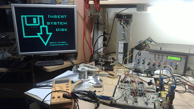
Very interesting, thanks ! I like this => “I laughed, my 16 color, 512 * 384 resolution simple VGA-card needed COOLING! ” :))
Without looking at the actual equation etc., here is what I can see:
U8 is without a clock, so it is combination logic dealing with video output (probably that does some RGB muxing) and can have race conditions. Not easily fixed in place as GAL have distinct modes unlike CPLD that you can simply use registered I/O (also clock pin is already used). You can clean up the timing, get rid of sub pixel glitches, timing/spatial jitters simply by using an Octal D-type latch to latch all the outputs to the 25.175MHz clock edge. i.e. use a 74HC574 in place of the buffer at U9 with very minimal changes to the PCB.
^ D flip/flop.
I never really meant that post to get public (nice though) so it was left more than short. This was actually a three-day quick project from start to finish so there is much room for improvement.
Added schematics for the GAL’s, enjoy! :)
2 layers of combinational logic inside GAL U3/U4 (2x delay) without resyncing to the clock. Some of the paths are only 1 layer.
Worse delay path is Data_Area_On which goes off chip and up to 3 layers. So for 10ns parts, that’s easily 30ns. That signal goes back to U6 which is clocked (not sure what is setup time, but probably around 10ns). 25.125MHz has a period less than 40ns leaving 0 ns margins which likely runs into setup time issue inside U6. So hot chip would just break it. Slipping setup time, things might get delay by a pixel and you can get thing moving around.
This is what I can see running timing in my head. If I can spot that in 5 minutes, there are much worse issue with the way the (or lack there of) design is done.
BTW: U3 is mislabeled in GAL schematic. It is actually U4.
Use a 7.5ns GAL for U3 (and if possible U4 too). Since there is up to 2X delay in some of the paths, that would be the most bang for the buck fix. A 10ns to 7.5n part change, would buy 5ns.
Some people are suggesting more modern CPLD but most modern CPLD are 1.8 Volt to 3.3 Volt and most wont work with 5 Volt chips. I can’t remember the layout of the 22v10 but I think it was 22 registers and 10 I/O. Exceptionally small compared to modern CPLD.
In any case it looks like the designer took this project from start to where it was here in less time that it would have taken for an express delivery.
I have a stick of 20 x 22v10’s here and I am not temped to use them lol. For 5 Volt I am using the Xilinx XC95xx(x)LS series that is 3.3 Volt but five volt tolerant. It’s Voh is above Vih for many 5 Volt chips though you will have trouble with some CMOS chips that have a Vih of about 3.33 Volts. The XC95xx(x)XL is based on the 22v10 or something like it, just many of them in one package with lots of interconnect between them.
Thumbs up, great project.
The 10 part means at most 10 flops or combination outputs.
Not that dissimilar to the video output circuitry from arcade boards of the time