If you ever wanted to build your own tube amplifier but you were intimidated by working with high voltages, [Marcel]’s low-voltage tube amp design might spark your interest. The design operates with a B+ (plate) voltage of only 40v, making it less intimidating and dangerous than many other amps that operate over 300V. It’s also incredibly easy to build—the whole design uses only 11 components.
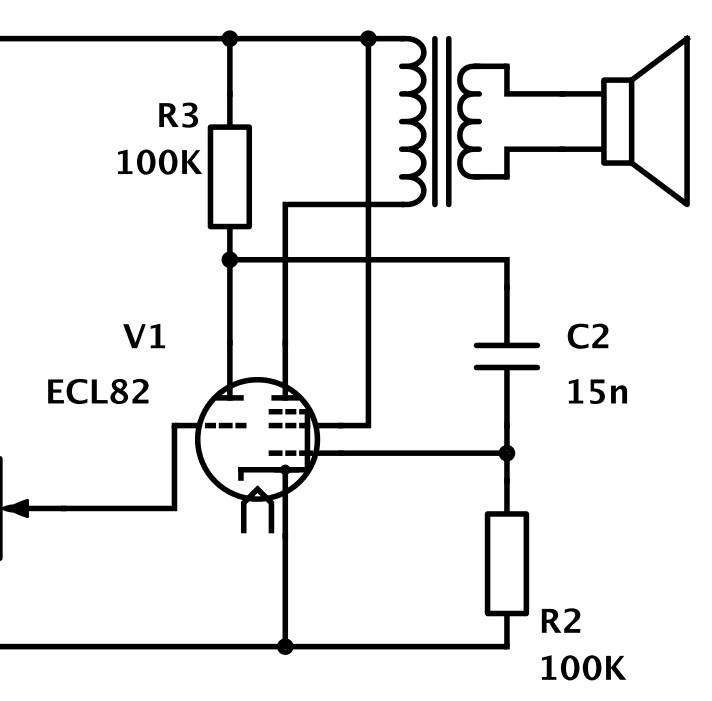
The amplifier is designed around the ECL82 tube, which includes both a triode and a pentode in one package. The ECL82 is practically an amplifier in a tube: it was designed for low-cost electronics like record players that needed to be as simple as possible. The triode in the ECL82 is used as a pre-amplifier for the incoming signal. The pentode is controlled with the pre-amplified signal and acts as a power amplifier.
[Marcel]’s amplifier also uses a PY88 tube rectifier instead of semiconductor diodes, making it an entirely silicon-free design. Although [Marcel] hasn’t posted up detailed build instructions yet, his simple schematic should be all you need to get started. If you want some more background information about tube amps but you don’t know where to start, check out our post on basic tube amp design from earlier this year.


This amplifier certainly isn’t silicon free. I’m sure those hollow-state devices have glass envelopes to hold the vacuum. The last I heard, glass in made with silicon. ;)
Quibbler! :-D
Glass is silica based. Silicone is something different. The article is accuratein this respect.
….just saying’ ????
….unlike my typos ????
Yes… cool… but for god’s sake… why? Other than the cool factor this is vastly inferior to a lower-cost, more robust, lighter, smaller, and safer system with IC’s.
Why? For the same reason you blink an LED with a microcontroller or print “Hello World” on any desktop computer!
Also, 1 watt tube amps make *perfect* guitar practice amps. 1 watt driven into that yummy tube distortion is just about exactly the volume limit for practicing in an apartment or a house you are sharing with others.
Isn´t the Amp single stage? I think it would sound ok and also be a great circuit to mod, like adding a tonestack.
Tubes are neat.
Too bad I’m too lazy to figure out American equivalent tubes for this though, maybe it would get half way put together if I did.
ECL82 = 6BM8 – Easy to find.
PY88 = 30AE3 – Never heard of it before.
One small issue with the schematic. No spec given for the output transformer. Yes, I could run the calculations, and figure out what would work, but I bet I am the exception in your audience.
Given that he is running on low voltage, and single ended, transformer choice is a bit far from typical.
I used an output transformer from an old tube radio, but i dont have its specifications. I measured 600Ohms and 1.2Ohms on its windings but I dont know how much turns it is.
Of course it would be good to use an appropiate audio transformer with the calculated values, but tube amplifier audio transformers are quite expensive, at least for this little circuit.
If you want to try it out, you can use for example a normal 230V / 12V transformer connecting the primary winding(230V) to the tube output and the secondary winding(12V) to the speaker. Dont expect no hifi-quality, but thats not the point, it just should work :)
I’ve got a 100V line transformer with these characteristics:
Power: 10 / 7,5 / 5 / 2,5 / 1,25 W
Impedance (primary): 1000 / 1330 / 2000 / 4000 / 8000 ohms
Output (secondary): 4 / 8 ohms
Could it really work in a single ended design like this?? I thought this kind of transformers would go into saturation so easily with the current going through the primary that would make them useless. But if your experience shows the contrary maybe I’ll give it a try. In that case, which would be the best impedance to choose on the primary?
I love colliding with the word “tranny” and suddenly playing a game of “Guitar Forum, Automotive Forum, or somewhere Far, Far Worse.”
In general I think projects benefit from a bill of materials. Even if you can’t find a particular part number to reproduce the project, it helps you find equivalents.
I’ve got fice tubes, all made to run on only 12 volts. I’ll have to make myself an amp sometime.
*five
The grid-leak biasing scheme is not what I found recommended by tube gurus. Positive half-waves of grid signals could easily become non-linearly distorted due to grid-cathode circuit breaking into conduction. It would be nice to use a resistor in the cathode appropriately sized so its voltage drop would exceed the peak pentode driving voltage. This way grid always remains negative with respect to cathode. The power output might suffer a bit.
Isn’t the distortion the main point of using a tube amp in the first place?
As noted in the article, running the PY88 heater at 6 volts means that the rectifier will give a very poor output. While the PY88 may be plentiful (in some parts of the world) and is a perfectly good rectifier normally, substituting a rectifier that uses a 6 volt (or 6.3 volt) heater would be better. As noted above,some idea regarding the output transformer would help. There are other tweaks that could be done too to improve the design, but the simplicity of this one would encourage newcomers to experiment.
You are comletely right. I made a small mistake in my description, the PY88 filaments gets the 30V it needs from the anode voltage (trough a resistor) so it heats like it should. Thank you for correcting this!
I have corrected the mistake on the project page. ECL82 filament = 6.3V and PY88 filament = 30V :)
it’s not the high voltages that put me off building a tube amp – its those pricey output transformers!
If you’re looking for cheap output transformers, Edcor has some good options. They have higher-end transformers with endbells too, which are still pretty reasonably priced. https://www.edcorusa.com/xseseries
Wow, a truly EMP proof amplifier.
During the built, I found out that the amplifier is much louder if I touch the output transformer (the iron shell) with my hand or if I connect it to the big power transformer’s iron.
I wonder If someone knows why this happens and could expllain this??
Thanks in advance.
Maybe just something grounding properly that wasnt before? The shell or the power transformer is grounded i’m sure. Not positive if the output transformer shell is supposed to be grounded or not
Pointless? Pointless! Of course it’s pointless, that’s what makes it cool. If you want practical, use an integrated circuit.
For years I’ve built amps with tubes, discrete transistors and chips of several types. Tube amps are by far the least efficient, but I don’t care. They’re simple circuits that get the job done with the fewest total components (count the transistors inside a power opamp chip some time). And a tube amp can look cool as well. They’re the lawn mowers of the electronics world: impossible to perfect, but also very difficult to get wrong.
“Very difficult to get wrong” often depends on the tube. Like semiconductor amplifiers, some tubes are rather more willing to turn themselves into oscillators than stable amplifiers. For this reason tube amplifier stages sometimes employ series resistors in the grid circuits to help prevent spurious oscillations, especially for power tubes. Quite a few tube builders learn this fact after the first project didn’t work as planned…
High transconductance (over ~7500 uS) tubes do like to feed back and oscillate. This is usually manageable with careful lead dress and stopper resistors. I’ve been using some Russian mil spec video pentodes rated at around 20,000uS (6J52P)and they behave fine even with long dangly breadboard leads as long as the grids are stoppered at the socket and the cathode, signal grid and anode wires are kept apart.
Low transconductance tubes like the ubiquitous 12AU7, 6SN7 and so on are pretty immune to misuse.
Because you can is the best reason to do anything, if you want to. And for that matter, 95% of what we do is ‘pointless’ if you look at the functional purpose of it. Better performance and practicality are fine goals to have, but they’re not EVERYONE’S goals.
Interesting project. There’s a store here where I live that has ECL82 tubes so there’s no reason not to try it.
But I think I’ll power it with a 48V supply. No problem feeding the heater of the ECL82 from the 40V with an appropiate resistor, no?
Kathode from pendode part of ecl82 is grounded but kathode from triode part of ecl82 is not shown on shematic?
That is my point too. Could say there is a 2-3k (or less) bias resistor but yes schematic is inconclusive.
Hey man reasoning like that are pushing this conversation into a philosophical area. Speaking of wich the entire mankind is useless because learning is simply not a valid reason (according to youe reasoning). What’s the point of living in complete predictability and never try something just for getting a feel of it? I tell you now: For humanistic reasons and pedagogic reasons. What? Yes to learn about humanity and to experience first hand some material issue that has neen known to man before but might not have a direct practical purpose today. Why are people replicating stone tools today? To learn about humans in the past.
Can I try with just any tube that has the right voltage specified? I have a bunch salvaged. All of them are 8 volts (have an 8 as the first digit).
How would I go about modifying this example to produce 12vdc @ 1-2 amps?
Save your money buy a tube let the currents flow inside watch the output signal grow we are glass we fall we break