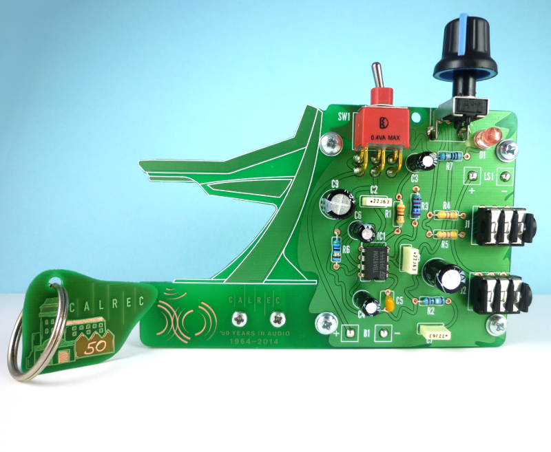
Though there is nothing wrong with the raw functionality of a plain rectangular PCB, boards that work an edge of aesthetic flare into their layout leave a lasting impression on those who see them. This is the philosophy of circuit artist [Saar Drimer] of Boldport, and the reason why he was commissioned by Calrec Audio to create the look for their anniversary edition amplifier kit. We’ve seen project’s by [Saar] before and this ‘Nutclough18’ amplifier is another great example of his artistic handy work.
 For the special occasion of their 50th anniversary, Calrec Audio contacted [Saar] requesting he create something a bit more enticing than their standard rectangular design from previous years. With their schematic as a starting point, [Saar] used cardboard to mock-up a few of his ideas in order to get a feel for the placement of the components. Several renditions later, [Saar] decided to implement the exact proportions of the company’s iconic Apollo desk into the heart of the design as an added nod back to the company itself. In the negative space between the lines of the Apollo desk there is a small perforated piece depicting the mill where the Calrec offices are located. The image of the mill makes use of different combinations of copper, silk and solder mask either absent or present to create shading and depth as the light passes through the board. This small piece that would have otherwise been removed as scrap can be snapped off from the body of the PCB and used as a commemorative keychain.
With the battery and speaker mounted behind the completed circuit board, [Saar’s] design succeeds in being a unique memento with a stylish appeal. There is a complete case study with detailed documentation on the Nutclough from cardboard to product on the Boldport website. Here you can also see some other examples of their gorgeous circuit art, or checkout their opensource software to help in designing your own alternative PCBs.


those wavy lines will make great rfi/emi antennae ;(
then again, this isn’t a high performance amp, so it probably doesn’t matter too much.
In electromagnetics PhD program, those wavy traces are fine.
What about in Soviet Russia?
In Soviet Russia, great emi will wavy you!
what asfwer said. wiggles don’t increase the loop area
Wrong. The loop area is the area enclosed by the current path and its return area. That’s basic geometry. I don’t think you clearly understand the term.
If the ground return path is kept at constant distance (e.g board thickness if microstrip and/or separation to ground), the loop area is proportional to the length of your tracks! By making the wiggle lines, you have intentionally increase the track lengths, hence the loop area.
So this increases the parasitics on the circuits – more track inductance, more parasitic capacitance.
More subtle than that…remember that linked inductance is canceled out when a conductor turns back on itself. Wiggle traces are used to increase propagation delay in PCB’s while minimizing mutual inductance with any sources of interference.
http://forum.allaboutcircuits.com/threads/zig-zagged-traces-on-pcbs.36175/
BTW there are some disagreement of the comments, so your quote is not a support of your view nor do they apply to the same layout. I can quote the comment from that link too and that basically states what I have said.
>kkazem: I’ve got to disagree with the SGT here. If you have a ground plane under the trace and zig-zag it, you are increasing both the trace inductance and capacitance to ground at the same time.
The track in the picture does not fold back as they are mostly bends, so there is minimal mutual cancellation in the inductance. Now if there are significant lengths of it that runs in parallel in close proximity, then you would get a bit of cancellation. Look at OP’s trace again and there are no parallel “overlapping sections” of the track to itself. Note the ground fills in area between the bends.
Anyway, the frequency of this audio circuit isn’t critical, so one can get away with that.
FYI: http://www.altera.com/technology/signal/images/fig2-7skew-minimization.gif
Now if you reduce the separation of the parallel sections of serpentine tracks like, you could have coupling between the segments and effectively reducing the effective delays.
I don’t see that type of tracks (where parallel section dominates) in the layout at all.
Very interesting project. I wouldn’t mind trying my hand at putting one together.
My only question is what the meaning of “Nutclough” is…
Ah, nevermind. I just found out that “Nutclough” is the name of the mill building that Calrec Audio resides in.
saw this posted on reddit a while back
bunch of people came in and chewed him out for the design
No surprise.
Though, I can’t find it on reddit. Would you happen to find a link?
Shut up and take my money already! I want one of these!!
I’m not a huge fan of the wavy traces with the still-just-plain-square-grid component layout, but I guess wavy traces aren’t really to my taste anyway. No harm.
That said, I really liked the design of the keyring. It leaves off copper where the windows are so it lets light through… that was neat.
Looks iffy, mechanically speaking, to me. The long, thin protrusion is just asking to be snapped off.
Sort of like the bottle opener on the Hackduino…