[Tim] discovered a simple way to measure the length of WS2812 addressable LED strips from a microcontroller. This is great for any project that can have an arbitrary length of addressable LED strip attached to it.
The simplest (and perhaps most reliable) way to measure strip length is by feeding the serial output pin of the end of the strip back to the microcontroller. The microcontroller keeps clocking bits into the strip until it receives data from the end of the strip. [Tim] didn’t want to run an additional signal to the end of his strip, so he found another solution.
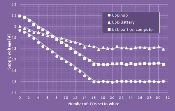
[Tim] used the ADC of his microcontroller (an ATtiny) to measure supply voltage droop as LEDs are turned on. Each LED draws around 60mA at full brightness, so [Tim] sequentially turned on each LED and watched the ADC for slight voltage changes. If the voltage changed, there must be an LED at that address. [Tim] does note that this method is extremely dependent on the power supply used and only works on short strips. Check out his blog post for more details.


It should be possible to extended this for arbitrary strip lengths by turning on only one LED (or maybe 2 or 3 for an easier to detect voltage drop) at a time and letting the lit LED(s) travel down the strip. Repeat this until no voltage drop occurs anymore, i.e. there is no LED at this position and the strip therefore must have ended.
Exactly that was what I wanted to say. I measured the current by turning on more and more LEDs from a 60 LED strip, and after a while the current does not increase, exactly as in his graph.
The problem is the bad supply lines in the strip. Connecting the 1 meter strip to good power at both ends increases the brightness significantly.
Measuring the voltage drop of only one LED may be difficult, especially for longer strips, because every LED has it’s own 100nF capacitor, that adds up to the overall capacitance, and the long line adds resistance and inductance. But it may be possible to let the LEDs flicker at a certain frequency, one after the other, and measure the resulting ripple. This should be easier to detect.
The AVRs in the standard Arduino have an internal 1.1V reference, this gives a LSB of 1.07mV. May be sensitive enough to detect the ripple via capacitive coupling. (Or even voltage doubling). Other micros, including some AVRs, have selectable gain amplifiers, that will greatly improve the sensitivity.
Overall, I like the idea. I’ve never thought about this.
I don’t see how capacitors and/or inductances would factor into a DC voltage measurement? The voltage drop in the copper lines would even add to the difference between on and off signal, so that’s a plus.
Well, yesterday, I tried to feed a whole 240 led strip at full brightness… With a standard PC power supply at one end, the voltmeter at the other end shows only 2.8 V (On the supply side, I got 4.70 V instead of 5.05 V… but the strip stared to go a bit warm on this side !)
Conclusion : double the strip by a thick wire to power it each meter if you don’t want to cook it (and avoid to put your arduino at the other end, as I stupidly did : at 2.8V it will freeze)
The simplest (and perhaps most reliable) way to measure strip length is by feeding the serial output pin of the end of the strip back to the microcontroller.
probably the simplest and most reliable way is a tape measure
That involves math though.
Simpler way: count the LEDs, you’ll know how many LEDs there are.
Last time I checked, that’ll require ‘Addition’, tends to be a part of math. :/
Counting becomes unreliable later into the night.
measuring voltage droop is a terrible idea IMO, just too many factors that will affect the reading. If you don’t want to add a signal to the bus you could use the last chip serial out to drive a high frequency signal (a simple burst will do) that modulates the power supply before a filter that precedes the WS chips chain. The uC will read that signal piggybacked to the power supply by feeding an i/o line through a filter, then do the count.
Or you could actually directly measure the current draw, instead of the voltage drop of the power supply. A small resistor, parallel to a Schottky diode to limit the drop to about 0.3-0.4V should do the trick. The main function of the resistor is to provide the quiescent current of the LEDs, which being sufficiently large to provide a reasonable voltage drop when an LED is turned on. The diode will limit the total drop for normal operation. Instead of the diode, you could also use a MOSFET to bypass the resistor when the detection phase is over, so there wouldn’t be any significant voltage drop.
I like the schottky diode to limit the drop by the sense resistor idea; nice.