Quick, how do you wire up an SPI bus between a microcontroller and a peripheral? SCK goes to SCK, MISO goes to MISO, and MOSI goes to MOSI, right? Yeah. You’ll need to throw in a chip select pin, but that’s pretty much it. Just wires, and it’ll most likely work. Now add a second device. The naïve solution found in thousands of Arduino tutorials do the same thing; just wires, and it’ll probably work. It’s not that simple, and Mr. Teensy himself, [Paul Stoffregen] is here to show you why.
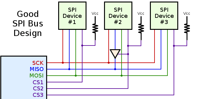
When using multiple SPI devices, a pullup resistor on the chip select lines are a really great idea. Without a pullup, devices will work great when used alone, but will inexplicably fail when used together. It’s not magic; both devices are listening to the bus when only one should be. Putting a pullup on the CS lines keeps everything at the right logic level until a device is actually needed.
How about the MISO line? Most peripherals will disconnect their pins when the chip select signal is active, but there are exceptions. Good luck finding them. There is an easy way to check, though: just connect two resistors so the MISO line floats to a non-logic level when the CS pin is high, and check with a voltmeter. If MISO is driven high or low, you should put a small tri-state buffer in there.
That just covers hardware, and there are a few things you can do in software to reduce the number of conflicts when using more than one SPI device. One of these methods is transactions, or defining the clock rate, setting MSB or LSB first, and the polarity of the clock. Newer versions of the Arduino SPI library support transactions and the setup is very easy. In fact, transaction support in the Arduino library is something [Paul] worked on himself, and gets around the problem of having SPI-related code happening in both the main loop of a program and whenever an interrupt hits. Awesome work, and a boon to the Arduino makers around the world.


Unfortunately, SPI transaction support doesn’t yet seem to be in Arduino mainline. Anyone know when it will be?
It’s in Arduino 1.5.8, and also planned for Arduino 1.0.7, which hopefully will release before the end of this year.
The 2 resistors are not to fix the problem, they are simply to determine if the problem (SPI device does not tristate) exists in the first place. The fix is to add a tristate buffer for the problem device.
If you are using a micro controller pin for chip select the code most likely sets the pin to high and low (driven both ways). This makes the advise about resisters actually counter productive because all they would do is slow the rate at which the pin can go to ground.
@MikeS – The problem occurs BEFORE code initializes the chip select pin. For example, when a library initializes device #1, its chip select becomes an output. But as it communicates with device #1, the chip select pins on device #2 and #3 are still unconfigured. If they happen to float at a voltage less than logic high, those other chips will “hear” the communication to chip #1 and possibly even respond by driving their MISO pins.
This is indeed a very real problem. For example, take a look at this bug report that’s been open for months on Arduino’s bug tracker.
https://github.com/arduino/Arduino/issues/2168#issuecomment-64298296
Also, the resistors do not cause any significant slowing of the signal. Resistance doesn’t do that, and the parasitic capacitance on resistors is very small. Resistors do consume a small amount of power when the chip select is asserted. That’s a very small price to pay for having SPI products “just work” when used together.
The correct solution is power sequencing the SPI slaves until after the communication lines are set up. Pullups are a current wasting hack.
Au contraire! jaromirs already covered the reason why they are a good idea in his comment. You can make it a pull-up of some number of megaohms if current is your sole concern, but having *something* during power up can make your life easier.
The pullups only consume current when the CS is active, and can be almost arbitrarily large.
The larger the pullup the more sensitive to noise the line will be. a 1Mohm pullup is almost useless. Wires (traces) act as antennas and as is they capture some electromagnic interference. 10Kohm pullups are most often used. At 5 volt this draw 500µA when the pin goes low, but the select line goes low only for the duration of transaction.
Powering up slaves devices in sequence require some i/o on the MCU and transistors to switch power line to devices. The pullup is simpler and cheaper. But even simpler is to initialize the i/o lines used as device CS before initializing any SPI device.
You don’t need to power them up one at a time. You simply set up the chip select pins with internal pull-ups in the chip, set them all to logic high, and then power your peripherials on all at the same time.
Then proceed with the rest of the initialization.
I always setup all the chip selects before communicating with any individual component, anything else is bad code that should be fixed not patched with hardware.
I do like jaromirs suggestion for a pull up/down on Miso.
Completely agree — I don’t see why you wouldn’t simply initialize all the CS lines before doing anything else. Such a simple programming guideline to follow and then there’s no need for pullups.
Perhaps you missed the context: the Arduino platform.
Now, if you’re an “Arduino hater”, your blood may already be starting to boil. If so, move on. Life is too short. But if you’re interested in improving Arduino as a platform or “ecosystem”, as I am, this is indeed very relevant.
Arduino is unlike a fully “bare metal” electronic design. With Arduino, people tend to buy breakout boards and shields, from a variety of different sources, or make their own (often copying a published board or schematic, but reusing the basic design and rarely writing their own software from scratch). This reuse of modules and software libraries enables the rapid prototyping that makes Arduino so awesome.
The trouble with “such a simple guideline” is the software components (libraries) for each device from different publishers. Each initializes its hardware, without any built-in logic to deal with whatever other hardware and software components are used. Requiring such a guideline would ruin the “rapid” part of rapid prototyping. It also would raise the bar far too high for novices, who are often able to achieve pretty sophisticated electronic projects when all the hardware and software components they picked happen to work together.
That’s what this is all about: to enable rapid prototyping, pre-made hardware modules and software libraries need to be able to work seemlessly together, without requiring the user to evaluate the hardware initialization of all of them, and craft (and debug) custom code before any of them actually work. That is “such a simple guideline” for a ground-up bare metal design, but it’s an absolute deal-breaker that ruins the rapid prototyping and low barrier to entry that make Arduino so valuable.
My hope, in publishing this article, and responding to comments like “why you wouldn’t simply initialize all the CS lines before doing anything else” is not to change how people do bare metal designs. That’s not the context here. This is about how companies like Sparkfun, Adafruit, Seeed and even Arduino design modules for rapid prototyping.
Following just these 3 steps will solve nearly all the compatibility problems that plague the Arduino world today. If you only to fully bare metal, 100% ground-up designs, that doesn’t matter to you. But for everyone using Arduino and a platform for one-off projects, or learning, or even very low-volume designs (where NRE for fully ground-up design is too expensive), having modules that “just work” is incredibly valuable.
It’s also fairly easy. But to move in this “everything just works together” direction, awareness of these issues by all parties making Arduino compatible hardware is essential. That’s why I wrote this article, and why I’m glad Hack-a-Day published it…. and why I’m hoping you (and everyone designing such hardware) can see how this would be valuable for rapid-prototyping modules.
That’s the problem with the way the user and the library interacts. User *should* initialize I/O etc on the first few lines in main(), but the whole Arduino thing dumbs down the user so much that the user might have no clue to do that. May be someone should start having to have init routines in the library that the use has to put in when main starts.
As Chinese whisper goes, a bad example on youtube/instructable copied by a few dozen and you ended up having an uneducated mass on the interweb.
Pull-up lines on CS lines is good to have because of power-up situation, when MCU still isn’t running and holding CS lines in high level . At this time, CS lines are in high impedance mode, so SPI slave can interpret it as logic low, as well as noise on CLK/MOSI line can be interpreted as valid byte, causing something nasty. Pull-up on CS line prevents this, but weak pull-ups (or maybe pull-downs) on MOSI and SCK lines is nice to have too.
It has nothing to do with number of SPI slave nodes, as CS line is usually push-pull type, not open-drain; single slave circuit without resistor on CS line is bad design.
I always include pull-up (it can be pull-down with no harm) resistor on MISO line. When all slaves are un-selected, this line floats, what is unacceptable for CMOS input of master node.
Buffer on misbehaving SPI device (when it doesn’t release MISO line, it shouldn’t be called SPI anyway) doesn’t solve the floating MISO line, resistors are here just to indicate it really floats. Leaving it in design is as wrong as having no pull-up on MISO line.
The correct solution here is a software one, not a hardware one. It is basic common practice in the micro world to initialize pins and put them in proper state as fast as possible in the start up sequence.
In this particular case it would mean making the CS pins as out and high, and then letting each SPI component sw initialize.
> Put them in proper state as fast as possible
Noise will be faster. Not always.. but once is enough to ruin your day.
A power source with slower than usual rise time is all it takes (depleted battery, current spike while charging decoupling caps, higher load from servo..). The CPU has brown out detector, but your SPI devices don’t.
> The correct solution here is a software one, not a hardware one
Both are needed. Software solution will not prevent hardware “failures” as described above.
I would worry more about default states for unprogrammed parts and default power up/reset state for parts if the particular I/O line is controlling something critical. So I would add pull up/down lines for those.
FYI: Most parts are designed to be programmed in system (for a production line) and probably in/after the test… So your design should not blow up before it gets its firmware loaded.
Most modern SPI slave devices would have their own power on logic or external reset inputs if they are of any critical nature or that they cannot be reset by software to be in a known state. Some level of floating until firmware early start up to initialize shouldn’t hurt the I/O lines too much. Thankfully, the better/modern chips would have weak pull-up/down built-in. But sometime you do have to over-ride the default pull-up/down for uninitialized FPGA/ASIC if it is driven something that needs the opposite logic level during a power up.
That is good practice, but not always the complete solution – which may be entirely situational.
The KIS-33R3S switching power supplies I use have a 15ms soft start. As they are capable of sourcing up to 3A, this is required to avoid voltage overshoot on startup. During part of that relatively lengthy ramp-up, the dsPIC33 isn’t capable of executing any code. Or longer, if the MCU’s power-on reset timer needs to be enabled for a clean startup.
Meanwhile, the W5200 Ethernet chip has already come up. But most of the time, it comes up in an invalid state, where MISO is continuously and actively driven low. And remains so until the MCU asserts the reset pin.
The W5200 datasheet is light on details. It doesn’t specify whether it has a power-on reset function or not, but if it exists, it obviously isn’t capable of correctly handling such a long soft start. It also doesn’t specify whether MISO can handle an overcurrent condition. If I were to add another device on the SPI bus with a similar issue, but that drove MISO active high, overcurrent damage might result – possibly even in just a few ms. In which case there would be no way to fix it in code, and a well-placed resistor or two would be necessary.
I have another project, a LED aquarium fixture, which I built before understanding this. During powerup and before the MCU can assert anything, the LEDs are briefly driven to max current. It’s harmless to the electronics (I knew better than to rely on the MCU for absolute current limiting). But it scares the fish, defeating the purpose of the “sunrise” function I programmed in to gradually increase lighting. Even a few ms of the full intensity of the LED array is surprising jarring.
@Bogdan – Your “correct solution” is indeed correct for custom design created by only 1 person or company, which is forever fixed and can’t be expanded or changes by replacing modules.
But consider a PC computer. A “correct solution” would not involve custom code in the first BIOS boot stage for all peripherals. Peripherals for PCs are designed to avoid incorrect behavior. Each is supported by a highly modular driver. No single piece of software initializes all hardware in a PC.
Arduino is much more like a PC than a fully customized, fixed hardware design. Users buy shields and breakout boards from a variety of sources, or make their own, often closely copying a published design and using the already-developed software library.
In a system where the hardware and software components come from many different sources, a more “correct solution” would look like the 3 guidelines in this article.
Two small comments on this:
1) Be careful with your choice of tri-state buffer. Depending on the system (maybe not an issue with something like an Arduino, but when you get into real high speed stuff), the delays caused by it could lead to issues with synchronizing with the chip select and clocking, etc. Again, this is mainly a comment for if you need 50MHz+ SPI somewhere.
2) When designing early on, pull-up resistors are often your friend. You can always determine later what values to use, or if they’re needed at all, when it comes to current draw, but not having them in your design (and not having the thought to have them in your mind to begin with) can cause you problems along the line, so this is valuable just for that.
You would more likely run into multiple issues with signal integrity issues well before a setup/hold time issues arises for most of the cases. e.g. Bad/long unterminated/non-controlled impedance (e.g loose wire, break in reference plane), lack of proper decoupling caps, bad return paths, lack of series terminations for the fast slew rates/extra stub lengths in the unbuffered SPI bus etc.
For people that know their SI to get to those speeds, they should already have calculated the setup/hold time and pick the right parts and bus topology.
FYI SD in the “SPI” mode doesn’t tristate its MISO pin *asynchonously*. You or your “library” need to release the bus properly by adding in extra SCK cycles for the synchronous after the /CS line is deasserted.
That’s isn’t how the SPI is supposed to work, but then again SDIO is what you are supposed to use to talk to SD media… There also might be broken SPI slave implementation out there and misuse of SPI HW for other protocols, the tristate driver is a kludge that makes it work.
“How about the MISO line? Most peripherals will disconnect their pins when the chip select signal is active, but there are exceptions. Good luck finding them.”
Electronnic design is not a guessing game. One must read datasheet cover to cover. If the device in use doesn’t tristate MISO when not selected use a better device. In most case the MISO should also be tristate during write transaction as reading data during those is pointless. I’m presently using a 23LC1024 in a project. and it is specified in the datasheet that SO (MISO) line is tristate when CS is high and when writing to device, no guessing game in it.
I’m guessing you’ve never bought a part from China before.
Why should I? I buy parts from renowned manufacturer that publish datasheets
Lol a sane person that realizes that time saved, sourcing ability, etc is worth more than the 50 cents that is saved. Bravo.
but if you are no longer *designing* something when you don’t know the parameters you are *designing* to. You are hacking things together and hack it until it “works” by luck.
This is hackaday
it has nothing to do with “better”, plenty of 4 wire spi devices drive the output all the time, nothing wrong with that. Driving the output diruign write isn’t pointless, it often means you can read and write at the same time
The W5100 Ethernet chip does not tristate MISO. Which isn’t mentioned in the datasheet as it should be, but in a separate app note which you might or might not have felt was relevant and bothered to read.
The more advanced W5200 (as used in the official Arduino Ethernet shield) does tristate MISO. But still doesn’t tell you that in the datasheet. Or tell you the characteristics of the power-on-reset function, including if it has one at all. Leaving you to find out on your own that it can sometimes power up in an invalid state where it *doesn’t* tristate MISO, unless you always reset it after power-up, which isn’t stated as necessary.
The nRF24L01+ transceiver will let you change the frequency while in RX mode, as long as it’s no more than a change of 100-200Mhz. More than that and it may stop receiving altogether, unless you disable and re-enable it. Again, no mention of this in the datasheet.
And if you alter the counter of a PIC24 timer, that’s running at the same cycle rate as the CPU, it loses a fixed number of cycles. Not just the one cycle it takes to perform the write, as one might expect. Microchip has some damn fine datasheets, but it doesn’t cover this.
These are all popular components, with detailed datasheets. Sometimes a little guesswork is required regardless. Being able to adapt is an essential skill. Limiting yourself to “renowned” manufacturers and familiar situations, not so much.
Instead of driving CS high (the alternative option shown), I’d suggest using the internal pullups. Less chance of damaging your AVR by an accidental short. Especially when running the AVR at 5V, shorting an output pin could fry the output driver for the pin, or even the whole chip.
At 3.3V it’s hard to get enough current to damage the chip, so it’s not much of a concern.
Another safety feature I recommend is BOD. Shorting an output pin will often drop Vcc, triggering the BOD reset, hopefully before any damage has been done.
This is a common misconception about the pins. When you have a pin as a output you are driving it high or low and selecting a pullup actually does nothing as this is a setting for inputs. Just cause you can set the register does not mean its actually being used.
In the Arduino’s AVR chips, selecting the pull-up is done through the PORT register while the DDRD register is set for input, so it is actually equivalent to simply writing a logical high to the output.
I am using 11 IMU with SPI interface at 2MH without any problem! Arduino UNO (ATMEGA 328p)
Why would the voltage on the MISO line float to half of Vcc if the MISO line is tristated?
Because that’s the threshold voltage on CMOS devices, where both the PMOS/NMOS transistors are equally on – halfway between the rails. It’s also why CMOS inputs really, really should never be left floating, since they end up sitting in the linear region and draw a bunch of current.
TTL logic devices don’t act that way with floating inputs, they just sit around the logic high threshold, perfectly happy. But with CMOS floating inputs = bad, just as a general principle.
FYI: Real TTL chips actually have a weak pull-up. In the datasheet, the IIL (Input LOW Current) parameter tell you what the pull up current is.
A CMOS I/O line would float to the last value for a bit because of its high impedance and parasitic capacitance. It will drift as leakage current would pull it whatever way that happens to be even somewhere half way. Hopefully it will settle on either high or low, but in few RC time constant when it is not, it might cross over the threshold region and cause cross conduction of the N & P-MOS.
It’s not an actual pullup. It’s the structure of the TTL input, which has a pullup on the input transistor base. The input low current is the amount of current needed to pull it low, but that doesn’t mean that there’s some competing pullup current you have to beat that’s always flowing (like in open-collector busses like I2C). If you leave a TTL input unconnected, and measure the voltage at that input, it won’t float at the rail, like a real pullup would.
I actually shouldn’t’ve said that TTL devices are ‘perfectly happy’ floating, although they won’t oscillate/burn themselves. They’re still more noise susceptible without a pullup. Short answer is you really should always have a pullup on everything, definitely on CMOS and on anything TTL where the input value might affect something.
http://en.wikipedia.org/wiki/File:7400_Circuit.svg This shows a typical 74XX input stage.
As far as the TTL input stage is concerned when you pull it up higher than its open circuit voltage, there won’t be current going in as the BE junction is reverse biased. The IIH parameter in the datasheet reflects that…
Sure you can pull it up externally, but you are not going to affect what it does inside the chip.
It would have been a good idea better explain why the resistors are being used.
-They are being used for the small time between power off and power on that is all. Between power being inserted and micro/ peripheral power up noise can be introduced and this can solve those issues by essentially telling the SPI peripheral “Hey your not being used yet ignore that garbage you are receiving”. (not really important most of the time)
-They get in the way 99.99% of the time (device powered up) as they are artificially pulling the output to one state BUT this is ok most of the time if the resistors have high values.
It is always a good idea to initialize all of your pins in software the second you start your micro up.
This is why everyone needs a scope. It’s not intuitive until you see a plot of this happening.
Do you know the state of the pins in your favorite micro before your code starts? During that short time between power applied (or other reset trigger) and when your code actually runs . . . the various bootloaders do different things; and it sometimes differs between a true power on and a reset.
As chango says, a scope helps see what is happening. But also knowing that it happens, and knowing whether it’s the hardware power on, the bootloader, or your code.
On some devices the SPI port is also very sensitive to noise, as it will often be rated to operate at many MHz and will use a high-speed input buffer. While that’s great for on-board work, it’s a recipe for double-clocking and other artifacts if the SI slacks at all. At a former employer, we had a ton of Aardvarks with bobbed tails (<2") for exactly this reason. If you're driving your device with any cable length at all, adding Schmitt trigger buffers to MOSI and SCLK will reduce the number of headaches associated with cable artifacts. Of course, the consequence is that Schmitt triggers cause their own setup and hold issues, but they're more predictable and manageable.
There’s an active Kickstarter campaign in its last week with the goal of an educational system for teaching I2C and SPI. There’s an arduino shield and a LOT of tutorials over at http://rheingoldheavy.com/. He already made his goal, so you’ll be seeing it happen if you get in now.
The kickstarter is at https://www.kickstarter.com/projects/1080546871/the-i2c-and-spi-education-system.
I’m okay with defensive designs, but this is just ridiculous. If you can accomplish the exact same task with less components, why not just do it? You should know if your chips do something dumb like drive the MISO if CS is not set, you should be driving your CS lines with P-P. Sure, there may be a break in the CS wire where a pullup would save your system, It could keep operating and ditch that one device, but even that seems a little excessive to me.
“Most peripherals will disconnect their pins when the chip select signal is active, but there are exceptions.” Punish the manufacturers for their insolence by mailing them lemons.
As the old adage says: A designer is not done when there is nothing left to add – but when there’s nothing left to take away.
The primary target audience is makers and companies selling Arduino compatible shields and breakout boards.
If you are designing your own fully integrated product from the ground up, and you’re writing all your software from scratch, you have far more control over the entire process, especially how all the hardware is initialized.
But if your design is a shield meant to work on all (or some) Arduino boards, which is clearly the context of this article, you really have no control over *all* the software. If you skimp on those cheap pullup resistors, conflicts with other devices are likely, because your library and other software libraries for other devices are developed separately. They initialize their hardware separately. You can’t possibly test your shield’s library with all others, and you certainly can’t test your shield together with all combinations of all others, on different boards and different pin-floating states. But you can add a pullup resistor to prevent the problem before it can happen.
Sure, it’s easy to say “You should know if your chips do something dumb like drive the MISO if CS is not set” in a comment. Indeed, the article says you should actually test whether your chip actually does this dumb thing. It turns out, quite a few chips do this. Some document it in their datasheets, but many others gloss it over. The point is not “you should know”, but rather “you should always test”. Doing so is very simple, requiring only 2 resistors and a quick measurement with a voltmeter. A dismissive “you should know” attitude is great if you always do know. But today there are indeed several Arduino breakout boards on the market that always drive MISO. A philosophy of “you should test” could have helped.
The goal is to get all makers and companies providing Arduino compatible hardware to improve their designs, so SPI-based product “just work” when used together on Arduino. As an engineer doing fully ground-up bare metal design, without reusing any libraries or other hardware, this probably doesn’t matter to you. But expressing such a dismissive attitude towards best practices for such a platform, simply because you can’t understand how a platform developed by many independent entities making hardware components meant to be used together could require different design choices, is, well, counter-productive.
I have a lot of respect for minimalist design, though in this instance (an Arduino shield)I agree the pullup is worth doing. 0603 resistors are only $5 for a reel of 5000, so the cost is insignificant.
We’re talking about Arduino users here, so you can’t count on them calling an init routine in setup() which would set your shield’s CE line high.
Paul, I’m sure you can tell lots of stories about users doing dumb things with your hardware…
Yes, I have a lot of those stories!
However, I’ve learned, behind most “dumb user” stories are stories of misleading product info, inaccurate or difficult-to-understand or simply missing documentation, or poorly designed hardware and software.
Last week, I patched Adafruit’s nRF8001 library (Bluetooth LE) to use SPI transactions, so it doesn’t crash when used together with a SD card. A couple days ago, I investigated why a multiple high-res graphical LCDs would not work together, which turned out to the MISO tri-state issue. Right after posting this blog, I resolved a months-old issue on Arduino’s bug tracker, which turned out to be a SD card hearing the Ethernet library initialization. A couple hours ago, I answered a question where the RadioHead library crashes when logging data to a SD card, which is almost certainly lacking SPI transactions again (fortunately, I’ve already patched those libs).
Arduino users deserve much better from all of us making and selling these shields and breakout boards.
I’m amazed no-one has pointed out that on many AVR devices the SPI interface pins are also used for the ISP interface. If you are not using a bootloader, or want to replace the bootloader, then mostly likely you’ll use in-circuit serial programming. Then you WILL need the external hardware pull-ups on /CS. Internal pull-ups won’t help because the IO is all tristated. avrdude knows nothing about which CS lines to configure so that approach won’t help.
Where is the upvote/like/favorite button here?
seems like i2c is a much better protocol than spi for multiple devices: 1.you need less wires 2. less messing about with all these extra parts to get it to work reliably…
Less performance too. I2C clock speeds are typically 0.1 or 0.4 MHz. SPI clocks are typically 4 to 25 MHz. I2C usually involves more protocol overhead, consuming more bits at those slower speeds. But I2C is indeed a great protocol when higher performance isn’t necessary. It’s simply not a replacement for SPI, due to it’s much slower speed.
I agree with the point that you’re trying to make; that both protocols have their own pros and cons, but I disagree with your assertion that “typical” shared SPI buses use faster clocks than I2C can handle (1MHz for most newer I2C devices and up to 5MHz for some). In my experience, typical uses for both protocols (configuration/ID EEPROMs, RTCs, temp sensors, IO expanders, IMUs, etc) rarely require more than a few dozen kbps bandwidth. 4+ MHz is only needed for rare high bandwidth applications like cameras, SD storage, and high speed ADCs/DACs. Chances are in those cases you don’t want to use a shared bus anyway.
SPI’s advantages include the simplicity of the protocol (and consequent ease of debugging), full-duplex capability, high maximum throughput, and compatibility with simple 74xx shift registers. It’s disadvantages include poor scalability when adding devices, differences in implementation details between different manufacurers due to being only a de facto standard, the potential for buggy firmware to cause catastrophic hardware failure in some cases, and the inability to support complex multi-master topologies.
I2C’s advantages include support for a large number of devices with minimal board/IO usage, inherent collision safety (all signals are open-drain), multi-master arbitration, slave clock stretching, ease of level-shifting (only 2 resistors and 2 FETs required), the ability to capture and decode all bus activity using only a dual-channel DSO, and the existence of an exhaustive published standard. It’s disadvantages include high complexity (both the protocol itself and the silicon required to implement it), low maximum line capacitance due to the use of pull-ups (resulting in one or more of: low bandwidth, short maximum bus length, and/or low noise immunity), lack of full-duplex communication, and requirement for device manufacturers to purchase slave addresses from NXP.
Another approach is to use a MCU like STM32F427 or such with boatloads of SPI and USART ports (STM32 USART ports can be used as SPI master ports). and then you can give each device its very own SPI port.
The site where this article was originally published has deleted all its blog content.
I republished the article here:
https://www.pjrc.com/better-spi-bus-design-in-3-steps/
Don’t know if it’s possible for Hackaday to update the link on an old article… or if anyone who gets redirected to this page from numerous links on the Arduino forums and elsewhere will ever see this 57th comment. But maybe better than nothing?
I came across this article because I am having problems using two ADXL345 Adafruit breakout boards with an Arduino Uno via SPI (how hard could it be..)
Here is the link to the forum post. It would be much appreciated if anyone could help :)
https://forum.arduino.cc/index.php?topic=679124.0;topicseen