Updating The Language Of SPI Pin Labels To Remove Casual References To Slavery

This morning the Open Source Hardware Association (OSHWA) announced a resolution for changing the way SPI (Serial Peripheral Interface) pins are labelled on hardware and in datasheets. The protocol originally included MOSI/MISO references that stand for “Master Out, Slave In” and “Master In, Slave Out”. Some companies and individuals have stopped using these terms over the years, but an effort is being taken up to affect widespread change, lead by Nathan Seidle of Sparkfun.

The new language for SPI pin labeling recommends the use of SDO/SDI (Serial Data Out/In) for single-role hardware, and COPI/CIPO for “Controller Out, Peripheral In” and “Controller In, Peripheral Out” for devices that can be either the controller or the peripheral. The change also updates the “SS” (Slave Select) pin to use “CS” (Chip Select).

SPI is widely used in embedded system design and appears in a huge range of devices, with the pin labels published numerous times in everything from datasheets and application notes to written and video tutorials posted online. Changing the labels removes unnecessary references to slavery without affecting the technology itself. This move makes embedded engineering more inclusive, an ideal that’s easy to get behind.

[2022 Editor’s Note: The OSHWA changed its recommended naming to PICO/POCI for “Peripheral In, Controller Out” and “Peripheral Out, Controller In”. Fine by us! I’ve updated this throughout the rest of the article because it doesn’t change Mike’s original argument at all.]

Continue reading “Updating The Language Of SPI Pin Labels To Remove Casual References To Slavery”

Better SPI Bus Design

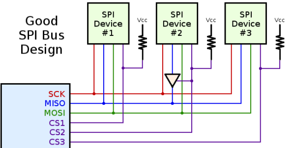
Quick, how do you wire up an SPI bus between a microcontroller and a peripheral? SCK goes to SCK, MISO goes to MISO, and MOSI goes to MOSI, right? Yeah. You’ll need to throw in a chip select pin, but that’s pretty much it. Just wires, and it’ll most likely work. Now add a second device. The naïve solution found in thousands of Arduino tutorials do the same thing; just wires, and it’ll probably work. It’s not that simple, and Mr. Teensy himself, [Paul Stoffregen] is here to show you why.

When using multiple SPI devices, a pullup resistor on the chip select lines are a really great idea. Without a pullup, devices will work great when used alone, but will inexplicably fail when used together. It’s not magic; both devices are listening to the bus when only one should be. Putting a pullup on the CS lines keeps everything at the right logic level until a device is actually needed.

How about the MISO line? Most peripherals will disconnect their pins when the chip select signal is active, but there are exceptions. Good luck finding them. There is an easy way to check, though: just connect two resistors so the MISO line floats to a non-logic level when the CS pin is high, and check with a voltmeter. If MISO is driven high or low, you should put a small tri-state buffer in there.

That just covers hardware, and there are a few things you can do in software to reduce the number of conflicts when using more than one SPI device. One of these methods is transactions, or defining the clock rate, setting MSB or LSB first, and the polarity of the clock. Newer versions of the Arduino SPI library support transactions and the setup is very easy. In fact, transaction support in the Arduino library is something [Paul] worked on himself, and gets around the problem of having SPI-related code happening in both the main loop of a program and whenever an interrupt hits. Awesome work, and a boon to the Arduino makers around the world.