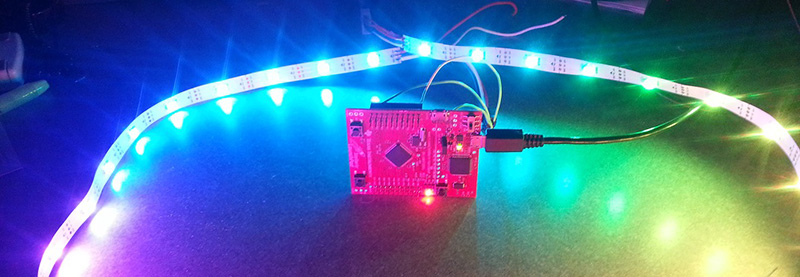
[Jordan] has been playing around with WS2812b RGB LED strips with TI’s Tiva and Stellaris Launchpads. He’s been using the SPI lines to drive data to the LED strip, but this method means the processor is spending a lot of time grabbing data from a memory location and shuffling it out the SPI output register. It’s a great opportunity to learn about the μDMA available on these chips, and to write a library that uses DMA to control larger numbers of LEDs than a SPI peripheral could handle with a naive bit of code.
DMA is a powerful tool – instead of wasting processor cycles on moving bits back and forth between memory and a peripheral, the DMA controller does the same thing all by its lonesome, freeing up the CPU to do real work. TI’s Tiva C series and Stellaris LaunchPads have a μDMA controller with 32 channels, each of which has four unique hardware peripherals it can interact with or used for DMA transfer.
[Jordan] wrote a simple library that can be used to control a chain of WS2812b LEDs using the SPI peripheral. It’s much faster than transferring bits to the SPI peripheral with the CPU, and updating the frames for the LED strip are easier; new frames of a LED animation can be called from the main loop, or the DMA can just start again, without wasting precious CPU cycles updating some LEDs.


It’s worth noting that, at least for the MSP430 processors that I’ve worked with, the DMA suspends the processor for 2 clock cycles for each byte or word moved. It’s still much faster than using the CPU, and doesn’t require all of the register saving and popping and returning, etc… but it’s not the DMA you might expect from a regular computer.
I’m definitely going to take a look at this because I will be needing to use DMA for SPI very soon and would like to see a good example.
Even if the CPU isn’t suspended outright, the DMA operations access data on the internal bus, possibly causing the CPU to be delayed if it also wants to access data on the same bus at the same time. On some chips you can adjust the settings for burst size, or bus priority.
MSP430’s DMA implementation is not true DMA. I’ve been disappointed by that fact for some projects, as well. The ARM architecture on the other hand, is a true DMA, which performs moving data from memory locations to peripherals and vice versa with cycle-stealing intervention or interruption. The only processor utilization required is to setup the DMA parameters, buffers, etc. Depending on the specific application, additional processor intervention will be required to either fill the buffers periodically or pull the data out of the buffer to do something useful. On Atmel’s ARMs (don’t remember about TI’s ARMs), the DMAs are even optionally double-buffered to prevent fragmentation of the buffer during those times when buffer manipulation needs to occur in the application logic. That’s really handy.
“…without cycle-stealing…”, rather.
Thanks for pointing this out, but I’m fairly certain that’s not an issue with TI’s M4 microcontrollers (at least, not with the Stellaris or Tiva C Series controllers). From the datasheet: “The μDMA controller’s usage of the bus is
always subordinate to the processor core, so it never holds up a bus transaction by the processor.
Because the μDMA controller is only using otherwise-idle bus cycles, the data transfer bandwidth
it provides is essentially free, with no impact on the rest of the system.”
Stupid question time… I just can’t seem to grasp this DMA stuff. Sure, it takes care of reading from memory and shuffling the data out to your LEDs (in this case). But, you still have to feed that memory location with information and you still need to check that the information you’ve put in there has been sent before feeding new stuff in, right? You could do that check via an interrupt I’m sure but to a novice it sounds pretty much like using any other peripheral like the EUSART? With the EUSART you feed TXREG (I’m using PIC terms here as that’s the only thing I’ve played with) with your data and then go about your day until the interrupt triggers letting you know that you can feed new data in.
What am I missing?
If you’re doing single values to a single location, nothing really (if it has hardware interrupt when it is complete).
Think of it like that register but on steroids where you can write a whole stack of values which the DMA then trickles out independently (and when it finishes it, it can cause an IRQ on the processor so you can quickly load in a new block or whatever). Depending upon the capabilities of the DMA engine, they can do more complex things like multiple destinations, multiple sources and various combinations so can be very flexible but it does depend upon the application as to how much it gains you (compared to the overhead of setting it up and feeding it new tasks on completion).
In the case of your UART register example. If you only had one value to send at a time, then it may not gain you much at all (if anything – given the setup costs, it may be actually worse).
However, if instead of your single value, you had several hundred then you can push all the values to the DMA at CPU speed in one block (v.fast with little overhead – if memory is shared then it may be as simple as giving the DMA the start address) and it can then sit pushing them to the UART register each time it becomes empty (as opposed to the CPU having to take an interrupt each time, stack registers, work out where it is now in the list, push the new value, un-stack any registers and then branch back to whatever it was doing).
It’s an economy of scale thing – if you do more then you need the extra ‘oomph’ (think of the DMA as a second processor, albeit a very specialised one, to help out from time to time).
Thanks for that. The chunk of data part was the missing piece in my brain. Now it makes a whole lot more sense and I’m going to have to see if I can use it in any future projects.
Another useful example (not made use of in my library) of a more complex feature is DMA ping-pong mode, where it continuously switches between transferring data into two different locations. I used this on a frequency analyzer I made a while back to allow me to fill up buffer A with audio samples from the analog to digital converter, then automatically switch over to filling up buffer B and generate an interrupt when A was full. While the DMA engine was filling up buffer B, my processor was running signal processing on buffer A (which I didn’t have to worry about the DMA engine overwriting). Once B is full, it switches back to A, rinse and repeat.
This mode of operation allowed me to ensure that I never dropped an audio sample (as the DMA engine was automatically ping-ponging back and forth between which buffer it filled with no required software overhead), and ensured that my ADC to memory function didn’t accidentally overwrite data that I was still using for signal processing.
So for my use case, I have here is that I want to have a single buffer in memory where I store the frame I want the LEDs to display. The frame buffer always stays in the same location, and I want to continuously send it out the LEDs, similar to how a monitor refreshes its display. The buffer I’m using now is 740 bytes long, which means that if I were using the SPI TX Data register, I’d be entering the interrupt handler 740 times to send out a single frame, and all I would be doing in that handler is clearing the interrupt flag and moving the next byte into the buffer (plus maybe a bit of logic to detect that I’ve transmitted the last byte and roll over back to the beginning).
With the approach I’ve taken here, I can set up my DMA engine to be transfer the entire frame to the SPI peripheral, then once the frame has been updated on the LEDs, start the transfer over again. I’m still entering the interrupt handler once data is done, but now I’m only entering it once the 740 byte frame is done transferring, not once every single byte is transferred. The first benefit here is it means I can spend fewer CPU cycles moving data to the SPI buffer. The second is that the processor doesn’t even have to be awake while this occurs. So if I don’t have any data to crunch, I can enter a low power sleep state on my processor, and the DMA engine is still cranking away, constantly updating my LED display :)
Awesome, thanks for the explanation. It’s all starting to click and I’m seeing possibilities for using it :) Now, if only I didn’t take several month long breaks between projects… Having to spend a few days getting back up to speed every time is pretty counterproductive to say the least…
I think it’s good idea to use for this task Maple mini board.
http://leaflabs.com/docs/hardware/maple-mini.html
http://polplaiconesa.com/tutorials/SPI+DMA.html
I’m sure some STM-32’s have DMA capabilities that can also operate while the “main” processor core is asleep.
Sleeping the processor core on STM32 reduces the power consumption somewhat, but the peripherals are the big power consumers when they are clocked. It’s a very simple matter to call “sleep and wait for interrupt” in your idle loop and most programs are already doing that anyway. Driving a couple of IO pins will use more current than the entire processor core.
Only played with Freescale K20 chip here.
The wait mode current on their M4+ is so high even with all clocks stopped @7.95mA (vs 17mA in run mode) to be useful. You are much better off if you can live with the much reduced clock (4MHz core) in very low power run mode with all peripheral clock enabled (1.1mA).
Even easier/better if you use an APA102 LED string which has an SPI-like 2-wire interface. No crazy bit-timing stuff, you just blast data into your LED chain at 4MHz+ using DMA. Works awesomely on an ARM.
(hoping I can type in an HTML link…)
for example.
i think the apa102’s are still more expensive than the WS’s
“…could handle with a native bit of code.” FTFY
https://github.com/ain101/SedecimWS2811