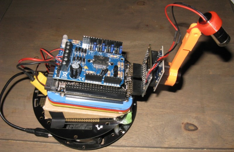
Somewhere down the road, you’ll find that your almighty autonomous robot chassis is going to need some sensor feedback. Otherwise, that next small step down the road may end with a blind leap off the coffee table. The first low-cost sensors we might throw at this problem would be sonars or IR rangefinders, but there’s a problem: those sensors only really provide distance data back from the pinpoint view directly ahead of them.
Rest assured, [Jonathan] wrote in to let us know that he’s got you covered. Combining a line laser, camera, and an FPGA, he’s able to detect obstacles that fall within the field of view of the camera and laser.
If you thought writing algorithms in software is tricky, wait till to you try hardware! (We know: division sucks!) [Jonathan] knows no fear though; he’s performing gradient computation on the FPGA directly to detect the laser in the camera image at a wicked 30 frames-per-second. Why roll up your sleeves and take the hardware route, you might ask? If we took a CPU-based approach at the tiny embedded-robot scale, Jonathan estimates a mere 10 frames-per-second. With an FPGA, we’re able to process images about as fast as they’re received.
Jonathan is using the Logi Board, a Kickstarter success we’ve visited in the past, and all of his code is up on the Githubs. If you crack it open, you’ll also find that many of his modules are Wishbone compliant, so developing your own projects with just some of these parts has been made much easier than trying to rip out useful features from a sea of hairy logic.
With computer-vision hardware keeping such a low profile in the hobbyist community, we’re excited to hear more about [Jonathan’s] FPGA-based robotics endeavors.


Amazing work, I have been trying to learn the logiboard with the Beagle bone black and have been unsuccessful. This is exactly what I have been looking for as far as placing a robotic foot on uneven surfaces using surface detection. I was thinking of using ultrasound but this is far more advanced.
Keep up the amazing innovation!
Project a laser grid and it could be used for traversing uneven surfaces while keeping the robot level. Should be a workable solution for active suspension on vehicles, as long as there’s a way to keep the camera lenses clean.
A line laser projector can be used in lieu of a flashlight in a dark room or outside at night. Aim it at the ground and look for distortions in the straight line. You can even use a simple laser pointer by rapidly swinging it sideways or even randomly waving it around to scan a rough map of what’s in front of you.
Congrats, you just invented Lumigrids.
I posted this “experiment” up a while back to demonstrate this kind of idea:
http://imgur.com/a/4RKVY#0
…and yes, that is my original Model M keyboard.
The laser grid would allow to construct a 3d map of the ground, but would require a corner detector (Harris or fast)instead of the sobel filter. Another way to reconstruct 3d is to use the robot odometry to compute the 3d by successive 2d measurement with motion.
The next part of this article series is coming up next week and we will cover the camera interfacing. A third part will cover the design of a 2d convolution operator that will be the base of the sobel operator in part 4.
It’s interesting that this uses an FPGA; SRS suggested just this when they designed a similar system in 2001:
http://www.seattlerobotics.org/encoder/200110/vision.htm
Given a bit more memory, the following sequence eliminates lighting issues: 1. With the laser line turned off, capture the camera image into a buffer. 2. turn the laser line on, and subtract the camera image from the buffer. 3. process the buffer as before to detect the position of the laser line.
Given a photodetector array instead of a camera, you can also modulate the laser diode at a fixed (fairly high) frequency, and then filter the output of the photodetectors to reject anything but that frequency. That allows direct detection without any real computing, but probably requires mechanical scanning.