The Raspberry Pi and its cool camera add-on is a great way to send images and video up to the Intertubes, but what if you want to monitor more than one scene? The IVPort can multiplex up to sixteen of these Raspi camera modules, giving the Pi sixteen different views on the world and a ridiculously high stack of boards connected to the GPIO header.
The Raspberry Pi’s CSI interface uses high-speed data lines from the camera to the CPU to get a lot of image data quickly. Controlling the camera, on the other hand, uses regular old GPIOs, the same kind that are broken out on the header. We’ve seen builds that reuse these GPIOs to blink a LED, but with a breakout board with additional camera connectors, it’s possible to use normal GPIO lines in place of the camera port GPIOs.
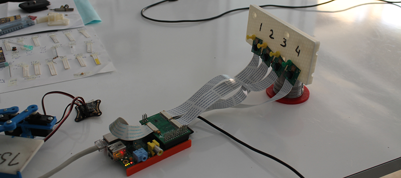
The result is a stackable extension board that splits the camera port in twain, allowing four Raspi cameras to be connected. Stack another board on top and you can add four more cameras. A total of four of these boards can be stacked together, multiplexing sixteen Raspberry Pi cameras.
As far as the obvious, ‘why’ question goes, there are a few interesting things you can do with a dozen or so computer controlled cameras. The obvious choice would be a bullet time camera rig, something this board should be capable of, given its time to switch between channels is only 50ns. Videos below.


Nice project, but $80+ for one multiplexer board seems a tad much
Yikes, yeah that does seem a bit steep. Not saying that it isn’t cool and I do have a use for something exactly like that but that would be a sizable chunk out of my projects meager budget.
No kidding. For that price you could almost dedicate a separate Pi to each camera. Which would also have the advantage of being able to space them at any desired distance, using WiFi or Ethernet. Whereas the distance using 15-pin cables is probably limited. That’s a rather important detail, but I see no mention of it.
Well may I ask what you expected to see from 16 RPI cameras? The Sydney Opera House perhaps? The Hanging Gardens of Babylon? Herds of wildebeest sweeping majestically across the plain…
@ steves
I don’t think you read Chris C’s comment; it’s not about image quality – He meant with the Multiplexer system you’re constrained to installing all the cameras in a small ~30CM radius due to cable length limitations, there aren’t many situations where having 16 cameras arranged in a small cube would be of any benefit
I did, and yes, I know, I know, and never mind.
Stereo 3D, spherical time-lapse, prototype DIY panono (https://www.panono.com/). So much could be done!
how about
– a storage warehouse
– a hatchery
– an orchard
no wildebeest required
Seeing all that would be cool. ;) But I was thinking more conservatively.
Take the example [Brian] provided of a bullet time capture rig, and expand on it. Say you want the ring of cameras 6m in diameter, to completely capture a standing person (that may also have arms raised), with lenses with a reasonable FOV. And you want 30 cameras. Note that I chose these numbers to represent what might be a realistic rig, without knowing the following result; I did not select or hand-pick them in advance to produce an unfavorable example.
Circumference is 18.84m, spacing between cameras is 62cm. So if [ryg] is correct about the 30cm cable length limit, and that limit is a strict one dictated by timing or other issues, then this mux won’t even allow you to successfully use TWO cameras per Pi! Being only 1cm short, perhaps you could alter the rig a bit or successfully push the limit, and at least get two cameras.
But four, like with the Holy Hand Grenade of Antioch, is right out. And at $80 per mux, you really need to be able to fully load it up to make it worth the money. So it’s of more limited utility than one might expect at first glance.
fundamentally the cameras/pi’s aren’t even close to being fast enough for bullet time, unless they were just simply shutter control. even with the software interpolation that the matrix used, they’re so far off it’d be unfeasible, then there is the matter of storage. spatially arranging the cameras is simplistic comparatively.
Not at that $80 price when doesn’t add processing power. I supposed one could make an imitation of this without real cost savings nor provide any real time capturing.
http://techcrunch.com/2013/11/05/bublcam/
you think you are providing a “practical alternative” but those cameras are fixed to each other, maybe you can find more useless junk to show us
Might want to re-read my comment. Are you intentional trolling in most of your comments?
I didn’t suggest the bubcam as the alternative. I am saying that this RPi solution can’t even do that type of work.
Ask yourself what do you see for a camera control board that have a very short wired length to a bunch of cameras? What configuration would that be? A *sensible* person would think about a cube or a sphere.
A solution that limit the processing/bandwidth of such camera is very restricted to what the end application would be.
4 cams?
i’m thinking of a biped working drone with two arms…
for that project, as i think, i would take stereoscopic sight with a fish-eyed overview and a tele-view-like view of the center of the image…
et voila (or “and viola”): HuBot eyes…
You can buy longer cables for the pi camera, however seeing as you can probably buy 3-4 raspis for the price of one of these boards it does seem pointless
This board was mentioned previously on HaD (http://hackaday.com/2014/07/27/hackaday-links-july-27-2014/) when it was just an Indiegogo project.
Now there are some better photos of the top and bottom board, it does look like they used two Fairchild FSA642 or equivalent MIPI switch chips. The enable control lines are connected to the /OE pin on the chip and the selection line is connected to both chips so you can control 4 cameras via 3 GPIOs. If you stuck an inverter on the enable line then you’d be able to do 4 cameras with 2 GPIOs but you wouldn’t be able to stack this board.
As for the price, it does seem a little high since the chip is only about $2 each but I guess after factoring in development costs, parts, PCBs and testing then it isn’t too bad. It is quite a specialised item as well so it isn’t going to sell in large quantities. If attaching multiple cameras to a single RPi interests you then it’d be easier to just buy this than make your own unless you needed a large number of them.
in this case, as the Broadcom number assigned to each new port created, I need to disable the LED cameras
in this case, as the Broadcom number assigned to each new port created, I need to disable the LED cameras
I’ll drop a plug for Adafruit… they sell RasPi Camera extension cables up to >> 2 Meters <<. Only $6 at that. Sounds like these would go well together. Just unboxing mine now…
Yeah the longer cable is definitely nice :)
How do they handle the I2C control of the camera? I guess you could just parallel them, but then agc/exposure commands will go to all camera’s at once, which seems undesired to me. The RPi also does quite a few I2C reads when initing the camera.
You can use an I2C mux (or equivalent) to segment the bus. Not sure if they have done so on this board.
Yeah, but the initialization commands should go to all cameras. It seems some intelligence is needed.
I2c doesn’t (normally) work like that: the imagers are designed to communicate in master/slave where the slave must ack its address. I2c does define a broadcast technique, but I highly doubt these imagers are listening to the broadcast address.
That said, most i2c devices have gpio pins to select alternative addresses so more than one device can share the same bus (think adcs and temp sensors). Failing that (more devices than alt addresses), there are i2c bus switches that allow the master to address multiple separate busses.
Finally, to get precise control over exposure timing you would need one gpio for each imager’s trigger/shutter input.
@brianbenchoff: “splits the camera port in twain” – not sure this is quite right, had me confused until I click through. It isn’t splitting the port in two – that makes it sound like you can add one extra CSI port for each device added. It is more like an ethernet hub with a fifth uplink port. So each additional unit simply adds four more ports – with the connection to the RPi’s CSI and GPIO being shared – without costing any of the existing CSI connections.
Yeah I’m not sure you could do bullet time rigs with this but could be useful for 360 degree surveillance type jobbies. Or those camera balls.
I think most of you miss the whole point. maybe the use of this hack is not cost effective or practical in your eye’s now, so go on and bash away. lets all remember that most discovery is made by people like all of us not big corps. or government. the use’s of some discovery made some time after and have applications no one would have ever predicted. but we (all of us ) look back and say NO DUH,IT’S A NO BRAINER. wonder why no one thought of that? well there’s always the possibility that the chicken had to come before the egg or vise/versa. so I guess who can ever predict to possible use so early in discovery. example[the invention of sonar]
I would love to use one of these for a 123d catch scanner that I am working on. The price rules it out though, $120 including postage to Australia. It is cheaper to have a dedicated pi for each camera. It’s a pity though. It would have saved a lot of cables…..
You could also use two MIPI CSI cameras per one pee compute module … if Broadcom wasnt a bunch of C^^^^rybabies
chip itself has ability to interface two cameras, first prototype had two cameras, industrial module pee has it routed out to edge connector
binary blob strikes again
This might be handy to check cars at checkpoints for bombs and such strapped to the underside, make a car-sized configuration of cameras that are recessed under a spot where the car stops with the cams and some lights and someone can quickly review the car.
Those sticks with mirrors they use now never seemed reliable to me at all.
And I’m sure some countries/orgs won’t might a bit of a upstart cost.
And seeing I don’t think it exists yet, you could well make a bundle.
I understand that it is not possible to realise a real time video using two cameras at the same time but my idea is to realise a time lapse with 24fps each camera (48 fps total) and switching the camera after every frame.
Is it possible with the maximum resolution of the Pi Camera (2592 x 1944 pixels)?
What do i do if I want to use the multiplexer and at the same time want to use gpio pins for oled display? Can i use the pins for stacking another multiplexer for oled display?
How can this board be modified to multiplex two RP MK2 cameras? I don’t need 4 just two. I gather MK1 cameras are OK. A single MK2 camera can be swapped around the ports and works in each location, unfortunately, as soon as you connect two cameras, they clash, and the whole interface locks up. I am assuming the cameras have identical I2C addresses so they can’t coexist. Either I2C must be muxed or else the cameras flashed with individual I2C addresses. Bit of a newcomer to this subject area but I have an application for two cameras to be switched.
Hello
Trying to understand how the concept works, as I have created a PCB to do the multiplexing myself ( not wanting to have pictures at the same time, but rather open one camera at a time)and handle other functions.
Right now I only use mux multiplexer to convery the signals from each pin of the camera from the RPi to each port of a camera, using 3 GPIO to decide which camera it goes to.
I am starting to think that the mux multiplexer are only really useful for the i2c tracks – do the rest of the pins need to be multiplexed using a CSI multiplexer like the FSA 642? Also, if only one camera is open at once there shouldnt be a problem of slave address being the same between different cameras no? Do I need to define a physical address for the PCB?
Also, someone (@Dojo) mentioned something about cameras being initialized – its not at boot that they are intiialized, it is as soon as you plug them right? Wouldnt they get initialized as soon as I open the desired track for the camera playing with the 3 GPIOS?
Thanks a lot for any help, having a lot of fun with this little project :)
I am in trouble with using IV Port v2 with code. How to use multiple camera board in detection of objects?
I can detect from only one camera while using this.
I am using IV Port IV in a project, anybody here can help me in detection of objects using multiplexing board?
I bought a IVPort V2 and after I connected it to the raspi, it burns down. Reverse polarity of an condensator.
Additional it didn’T work at all. Normal cameras are working on my board – but not IVPort V2.
But the really bad part is, that non of the github issues related to the board or software get an answer from the vendor.
This kind of support channel is dead.
Is there an alternative out there? StereoPi is great – but just RASPI 3 only. I want use RASPI 4 with USB 3
(required for Google Coral TPU).
Greetings
Andreas
Same problem here not a reverse polarity issue but the board it’s not working at all… I checked the board and found that they placed an I2C multiplexer but they didn’t drive it… it seems just a joke (100€ joke).
The problem it’s not on the i2c multiplexer.. it should be driven trough i2c command itself A0, A1 pin are used just to set the slave address. The issue is still there anyway (i.e. the board it’s not working)…