Around these parts, we generally celebrate clever hacks that let you do more with less. So if somebody wrote in to tell us how they used multiplexing to drive the front panel of their latest gadget with fewer pins on the microcontroller than would normally be required, we’d be all over it. But what if that same hack ended up leading to a common failure in a piece of consumer hardware?
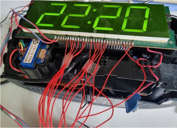
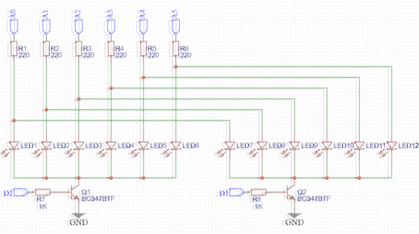
As [Jim] recently found out, that’s precisely what seems to be ailing the Meaco Arete dehumidifier. When his stopped working, some Internet searching uncovered the cause of the failure: if a segment in the cheap LED display dies and shorts out, the multiplexing scheme used to interface with the front panel essentially reads that as a stuck button and causes the microcontroller to lock up. He passed the info along to us as a cautionary tale of how over-optimization can come with a hidden cost down the line.
Continue reading “Clever Engineering Leaves Appliance Useless”