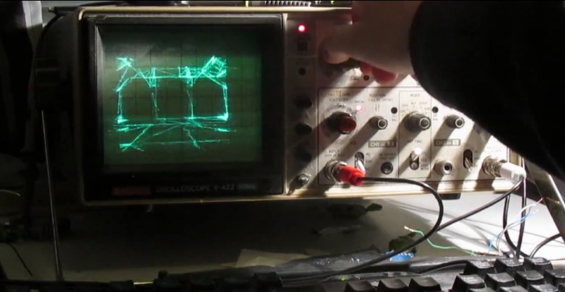
[Pekka] set himself up with quite the challenge – use an oscilloscope screen to display Quake in realtime – could it even be done? Old analog scope screens are just monochromatic CRTs but they are designed to draw waveforms, not render graphics.
Over the years Hackaday has tracked the evolution of scope-as-display hacks: Pong, Tetris, vector display and pre-rendered videos. Nothing that pushed boundaries quite like this.
[Pekka]’s solution starts off the same as many others, put the scope in X-Y mode and splice up your headphone cable – easy. He then had to figure out some way to create an audio signal that corresponded to the desire image. The famous “Youscope” example demos this, but that demo is pre-rendered. [Pekka] wanted to play Quake in realtime on the scope itself, not just watch a recording.
With only so much bandwidth available using a soundcard, [Pekka] figured he could draw a maximum of about a thousand lines on screen at a time. The first headache was that all of his audio cards had low-pass filters on them. No way around it, he adjusted his ceiling accordingly. ASIO and PortAudio were his tools of choice to create the audio on the fly from a queue of XY lines given.
To tell his audio engine what lines to draw, he solicited Darkplaces – an open source Quake rendering engine – and had it strip polygons down to the bare minimum. Then he had to whip out the digital hedge trimmers and continue pruning. This writeup really cannot do justice to all the ingenious tricks used to shove the most useful data possible through a headphone jack. If this kind of thing interests you at all, do yourself a favor and check out his well-illustrated project log.
In the end [Pekka] was not entirely happy with the results. The result is playable, but only just barely. The laptop struggles to keep it simple enough, the soundcard struggles to add enough detail and the scope struggles to display it all quickly enough. At the very least it sets the bar extraordinarily high for anyone looking to one-up him using this method. There is only so much water that can be squeezed from a rock.
See the video below of [Pekka] playing the first level of Quake.
Thanks to: [Mr. Jay], [james], [gudenau], [AltMarcs], [Alogus], [Daniel] and last but not least [ProfFartSparkles] who all really wanted us to feature this hack and sent in a tip.


I don’t even see the code. All I see is blonde, brunette, redhead.
The technique does remind me a lot of “Waking Life” 2001.
Waking Life and A Scanner Darkly used a “rotoscoping” technique, which oddly enough is similar to the oscilloscope method above.
Very cool hack. Very, very cool. @Koplin, my thoughts exactly. ;)
Now this is what I think of when someone talks about a hacker; of course, it helps that my exposure to hacking was through old (to this younger generation) magazines like Radio Electronics and their Hardware Hacker column and not the other stuff that the media calls “hacking”. Yeah, the hardware is having trouble doing what he asked it to, but that it’s working at all means he did what he set out to do.
Diggin’ it as-is, but just a little more work, and this could be a laser-show.
Galvos would limit the bandwith even more, the code would need a LOT of work to lower the amount of rendering needed and optimize the movement so that the galvos have a chance of keeping up…
I wonder if you could divide up the task among 4 or 6 sets of galvos. Keep the angular range to a minimum to keep scan speeds up.
This is very relevant to my interests! \o/
Liquid crystals might be able to steer a laser beam and maintain a narrow beam. Piezos however don’t seem to be agile enough. Anybody know more strategies for this?
If you had a custom made piezo mirror…thing…, I’m pretty sure they would be able to beat electromagnetic galvos in terms of speed. Not sure how difficult it would make the optics (very small deflection).
But it would still require a lot of code optimalization, possibly some form image feedback for a control loop so that the lines are not so squigly :D
Piezos have a bit of non-linearity in them too, but presumably the bigger difficulty lies in optics which don’t distort the beam. A cheap, aftermarket fisheye lense for smartphones might actually suffice…
Here about the “piezo mirror…thing…”: http://www.mirrorcletech.com/devices.html
but it’s not cheap.
Hm. For a maximum speed DIY galvo I think I’d start with an electrostatic speaker using a mirrored Mylar diaphragm and some ITO drive electrodes. Beam quality is likely to be crap, but speed shouldn’t be a problem. A bit of mirrored microscope slide cover should fix beam quality, but won’t help the speed. Oh well, one more thing for the stack of stuff to experiment with “when I have free time”
@AltMarcxs: That’s a nifty optical scanner chip. I took some advance control classes in graduate school, I’d love to see if I could exceed that chip’s speed specifications with the right controller.
MEMS mirror-systems have been used in projection-TVs for quite some time. I dunno whether those mirrors are simply binary, or what… but clearly they’ve got exceedingly-fast motion(?) and huge resolution. They can be bought from surplus places for *really cheap* with *zero* documentation. It’s a curiosity, anyhow.
I wouldn’t call that barely playable, I would call it easily playable.
Then I dare you to go to Quakecon and place using that setup.
Didn’t know you had to place in a competition with your rig to make it qualify as playable…
Wow, not that is pushing the envelope, nice work!
Crazy stuff, especially the hacked engine to display vertices only.
Guess it had to be the sound card, since some analog circuitry to convvert VGA RGB into monochrome (a simple resistor adder) and some ramp generators for Hsync and Vsync would have been much easier.
Just wodering on which demoparty this will be displyed :)
It would be simply enough to use 2 colour components as X and Y. Scopes don’t have much res anyways, so 8-bit colour depth is probably enough. The left over colour component to control beam intensity (Z?)
Hate to write the rendering code for that,
If you check the “vector display” link in the article, ( http://hackaday.com/2014/02/19/vector-display-output-on-an-oscilliscope/ ) frequent Hackaday featurist Charles Lohr did just that. Used the red and the blue of a VGA port on his laptop to display stuff on his scope. So, if you’re not using an audio port hack, you could have massively more bandwidth but – as others pointed out – that’s not necessarily the only problem.
It seems that there’s 3 constraints all coincidentally being pushed to their limits already, so, getting breathing room on one of them probably isn’t sufficient to get much farther.
I used Tek XY displays in the 80’s (The little ones that were a simplified storage scope with the a signal amp on each axis instead of a time base) and used 12 bit DACs for plotting. The CRT drivers, amplifiers, and spot size can most definitely handle a lot more than 8 bits. Vector General sold big vector displays in the 70’s for minicomputers for just that reason. It was a long time before raster graphics caught up with vector displays.
If he wants to go the next step, and the hard work is doen with the stripped and fixed up code to generate vertexes, two DACs, 4 op-amps and 2 carefully chosen caps will get pretty straight lines without needing the extra data points. Check a Battlezone machine that used slow 8 bit data and “linearized” by using only part of the charging curve and truncated (changed to new vertex). Hmm. I still have one of the Tek XY displays and it works. My my!……..
Using 2 color channels to control the X/Y inputs might actually be a rather good idea! The bandwidth is definitely much higher than any audio output could ever provide. Even at low resolutions and refresh rates, the pixel rate would probably be far to high for a cheap old scope to keep up with (I recall old VGA cards had RAMDAC’s in the order of 300-400MHz), but that could be solved by either drawing several consecutive pixels in the same color, to allow the scope front-end to catch up, or (probably better) interpolate a few values along each line, such that each line on the scope consists of several pixels from the VGA output.
Considering the phosphor of a regular, analog scope is fairly slow to decay (by design), the refresh rate doesn’t need to be very high, so a huge number of line segments could be visible at the same time. Maybe you could have to redraw each line several times to get sufficient brightness though.
One potential problem would be the horizontal and vertical retrace from the VGA card; during those times, you can’t actively control the color component outputs, and I’m not quite sure what the signals would be during the retraces. I’d think the signals would be held low, to prevent the retrace lines from showing up on the monitor, but it’s also quite possible this would be taken care of in the monitor itself, I don’t know the specifics of this.
Analog oscilloscopes are amazingly flexible pieces of equipment. Even though I still have one, I rarely use it, because digital scopes offer many features that are simply not available on older analog scopes, but there is something about the analog ones that makes me feel all warm and fuzzy.
I can’t find a reference, but I recall reading about an engineer, many decades ago, who placed a phototransistor in front of an oscilloscope, fed the signal back into the oscilloscope, and used this as an arbitrary waveform generator, by covering part of the tube with a paper cut-out of the desired waveform. When the dot was behind the paper, very little light would reach the phototransistor, which was probably on the low-side of a resistive divider, such that this would cause the voltage on the output of the circuit, and thus the input of the oscilloscope, to increase. This would make the dot rise on the display, until it was no longer covered by the paper. When the dot was completely uncovered, it would emit so much light that the voltage would decrease; this way, the dot would always keep “hugging” the edge of the paper, being partially covered by it. With this incredibly simple and elegant setup, the engineers could generate complex waveforms, although somewhat limited in slew-rate and the width of the screen, by simply cutting the shape out of a piece of paper!
Fascinating. Thanks for sharing, I’m going to try that sometime!
Ohw, that is a pretty neat trick!
I know tektronix in the 1980’s made very high speed ADC’s by writing on a diode array in a crt. So you had the classical CRT view screen and antiparallel next to that a smaller CRT that initially sampled the signal and draws it on a diode array “screen” chip. This screen capture was constantly written to the normal CRT. So it was high speed capture and storage.
In the blanking period, the three color channels are clamped to the black reference level (a bit above 0V usually), allowing the monitor to zero its amplifiers periodically. Unless it’s a sync on green monitor in which case the green channel only gets the xor of hsync and vsync anded with it during this period.
If I understand your comment correctly, using a modified VGA signal would still result in a signal for a raster display. However, you cannot modulate the brightness of a dot on a regular oscilloscope (without extensive modifications), and I also doubt scanning the entire screen many times per second would result in any significant brightness if you could.
A thousand lines visible at any time is still impressive, but you also have to consider that you can’t turn the beam off when moving from the end of one line to the beginning of another. You can’t connect them off-screen either, because you would still see the reflection of the beam hitting the side of the tube.
What amazes me is that someone can put this much effort into and actually finishing a project that is rather awesome, but ultimately completely useless. This is not meant as a insult; I admire the determination.
Some of the analog scopes has a Z-mod input (at the back) for intensity modulation. This is a feature not typically found on digital scopes. My dual mode analog/digital has Z-mod, but lacks the Y input while my other digital scope has X/Y, but lacks the Z-mod.
http://www.logwell.com/tech/oscilloscopes/Z_mod.html
I am blown away!
I wonder if an Arcade XY monitor could keep up with this.
Interesting approach, but flawed? it generated a lot of edges you normally dont see – plains get divided into triangles on the scope screen
I wonder if it wouldnt be more optimal to drop textures (or texture resolution), render BW/grayscale and extract edges from that, you can have few passes untill you get the max edge count your scope can handle
The reason is that they are rendering in a fan-out pattern to render surfaces. It can be quirky if you try to use fan-out triangle patterns for everything, usually use a combination of patterns but a scope might be too limiting for more complex patterns.
His new nickname – “The Scope Whisperer”.
This is super awesome!
I’d bet the audio card’s output low-pass filter is a first or second order filter. If you measure it’s properties and multiply your rendered audio by it’s inverse, I bet you can get 2-5x more bandwidth. (the resulting digital filter should only be 4-6 MAC’s per sample per channel. i.e. fast)
P.S. I like the VGA suggestion as well. The scope and processor will be the bandwidth limit then.
The sigma delta audio DAC I looked at has built-in low pass digital brickwall filters with around 70dB attenuation. That’s not something you can compensate easily.
Some oversampling DAC might requires additional external passive filters to improve performance, but mostly position at a few hundred kHz for blocking oversampling frequency out at MHz range.
The DAC frequency response plot of AK4556 at 192ksps do go out to 80kHz or so with less than -1dB drop.
May be it is a function of the analog filtering after all.
Are there scopes that let you do dual channels in X/Y mode? If so, you could double the number of polygons you display.
You can in some fancy digital oscilloscopes. It would be nice to see how this looks like in them.
I wonder how playable it would be (both in performance and in visuals, ie. Being able to distinguish walls and doors) if he were to drop the internal verticies of each polygon and just render the edge verticies?
Less lines to draw should give him more breathing room.
agreed, you can keep the draw distance up and there will be significantly less vertices to draw with edge detection
also adding the hud health/bullets back too would be mondo cool
Heck, compared to the extreme darkness of original Quake (without bumping up the gamma setting a whole lot), this looks more playable. You can see where you’re moving!
WOW!
this is amazing! I cant believe this was done just using a 96kbps sound codec, with no beam blanking.
But then again, the sound codec produces strong Oszillations…
Next step should be to build your very own output card, using a fast DAC, and Beam Blanking.
May a pack of sex-starving ladies find their way to this guy’s crotch by day’s end. This is a great piece of work and deserves a very loud applause. I’d never expect this image quality from a vector-render of Quake. Well done!!
This reminds me of the ultrasonic bat-vision from the dark knight! Very cool!
with all the posts showing the rendering of 2d and 3d shapes with ac sine waves on this site lately it makes me wonder if someone could use the same technique to shape similar designs from ferrofluid.
Maybe a use for those ancient camcorder CRTs, a miniature waveform generator using a micro B/W or colour LCD salvaged from a more recent camcorder; these also pass near infrared light quite well.
Has anyone tried making an old Gen 0 night vision tube (the 13.5KV ones) into a ‘scope using this technique yet? Ought to be reasonably good resolution and fairly compact.
Now that is impressive!
Crazy Finn in the midst of winter … What did you expect? New OS? Oh wait … (Yes I know that Torvalds is Finnish Swede).
(best Darth Vader voice)
Impressive. Most impressive…..