In the last video I demonstrated a Universal Active Filter that I could adjust with a dual-gang potentiometer, here I replace the potentiometer with a processor controlled solid-state potentiometer. For those that are too young to remember, we used to say “solid-state” to differentiate between that and something that used vacuum tubes… mostly we meant you could drop it without it breakage.


The most common way to control the everyday peripheral chips available is through use of one of the common Serial Protocols such as I2C and SPI. In the before-time back when we had only 8 bits and were lucky if 7 of them worked, we used to have to memory map a peripheral or Input/Output (I/O) controller which means we had to take many control and data lines from the microprocessor such as Data, Address, Read/Write, system clocks and several other signals just to write to a couple of control registers buried in a chip.
Nowadays there is a proliferation of microcontrollers that tend to have built-in serial interface capability it is pretty straightforward to control a full range of peripheral functions; digital and analog alike. Rather than map each peripheral using said data and address lines,which is a very parallel approach, the controller communicates with peripherals serially using but a handful of signal lines such as serial data and clock. A major task of old system design, mapping of I/O and peripherals, is no longer needed.
Using Digital to Control Analog
Two serial interfaces have risen to the top of the heap as far as prevalence: I2C and SPI. I2C is a more sophisticated protocol that arbitrates who should do the talking and is basically bidirectional meaning that the data input pin can double as a data output. I2C also implies peripheral IC’s that have pre-assigned addresses and since the receivers are addressable, all can be connected together on the same I2C bus. I2C is all the better if you don’t have to debug it which I have had to do in the earlier days of the protocols existence, (but that was a while back).
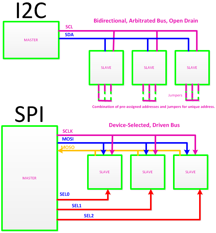
I consider SPI, short for Serial Peripheral Interface, to be more of an attitude than a strict protocol as I have seen various specifications for how clocks and selects work so it is usually worth checking the details if designing for production. At the heart of SPI is a separate Chip Select for each device and a dedicated data input and output. On the plus side the data lines don’t have to worry about being bidirectional or having to deal with contention, and so they are designed as true active high and active low driven lines whereas I2C has a passive pull-up which may limit maximum speeds or loads.
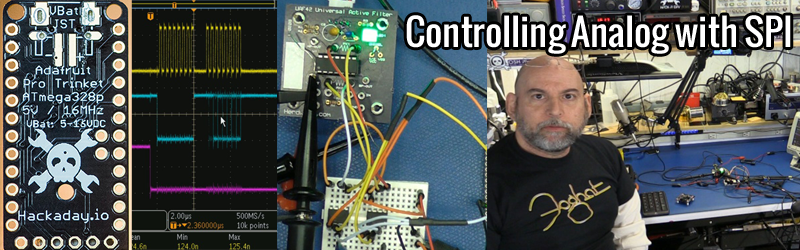
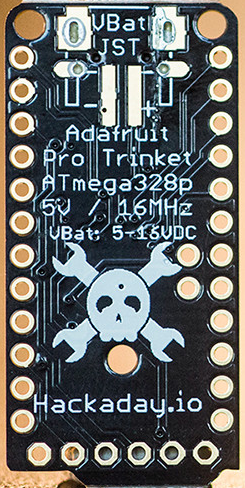
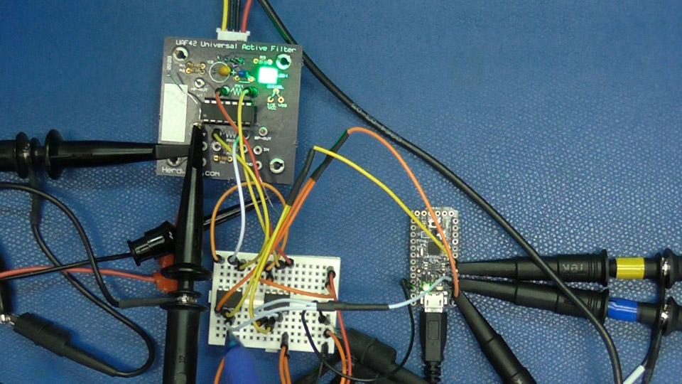
In this instance I chose the digital potentiometer that I wanted and let that determine the Serial Protocol. In the video you will see the various controllers and processors that I looked at and settled on the Hackaday Pro Trinket for the simple reason it has a Hackaday skull on it.
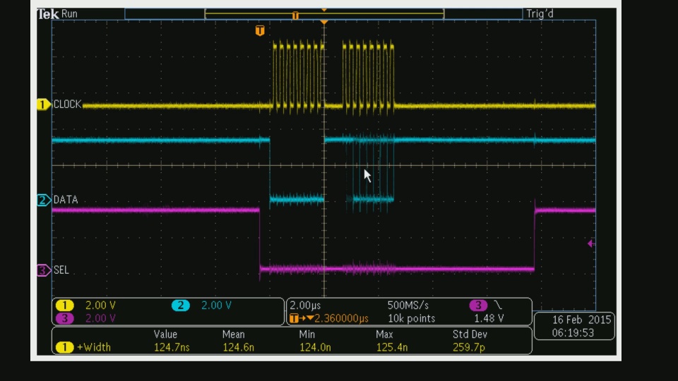
A quick download of the IDE and I was able to speak to the module via the bootloader. Perusing the built-in examples gives us not only an SPI based project written in ”C” but also one of the two SPI examples is for a digital potentiometer. I have elected to use the MCP4161 Digital Potentiometer and even though it is a different part than the SPI example, the changes needed to the code are minor. Looking at the datasheet we find that writing a value of zero first and then a second value which indicates the resistance value of the potentiometer as a $00-$FF hexadecimal range of 256 steps. The example code sits in a loop incrementing both bytes so I changed the first byte to $00 and left the incrementing code alone as being useful for our demonstration here and recompiled.
My original plan was to demonstrate the digital pot and the filter it controlled on one PCB but ran into problems with the compatibility of too many power supplies, the grounds and even the voltage drop of the long USB cable I used to drive the demo from across the room. Using a small solderless breadboard it was straightforward to hook up the digital pots to the SPI bus and then swap them in place of the dual ganged pot.
If you didn’t see the previous video, I use a sweep frequency generator to demonstrate the effects of our adjustable filter. The function generator starts by outputting a low frequency and then quickly sweeping up to a higher frequency.
This has the effect that a properly triggered oscilloscope displays low frequencies on the left side of the display and high frequencies to the right. The frequency response of the filter as it moves between the low and high frequencies is seen as moving between the left and right sides of the display where the x direction indicates frequency.


Like our last demonstration the filters are seen moving up and down the range only now it is under the control of a simple C program and not a manual adjustment. Picture if you will, then an analog synthesizer that instead of a carefully calibrated control voltage to manage oscillators, filters and other effects, all while tracking each other closely without worrying about linearity or temperature affecting the accuracy of the control.
An Analog View
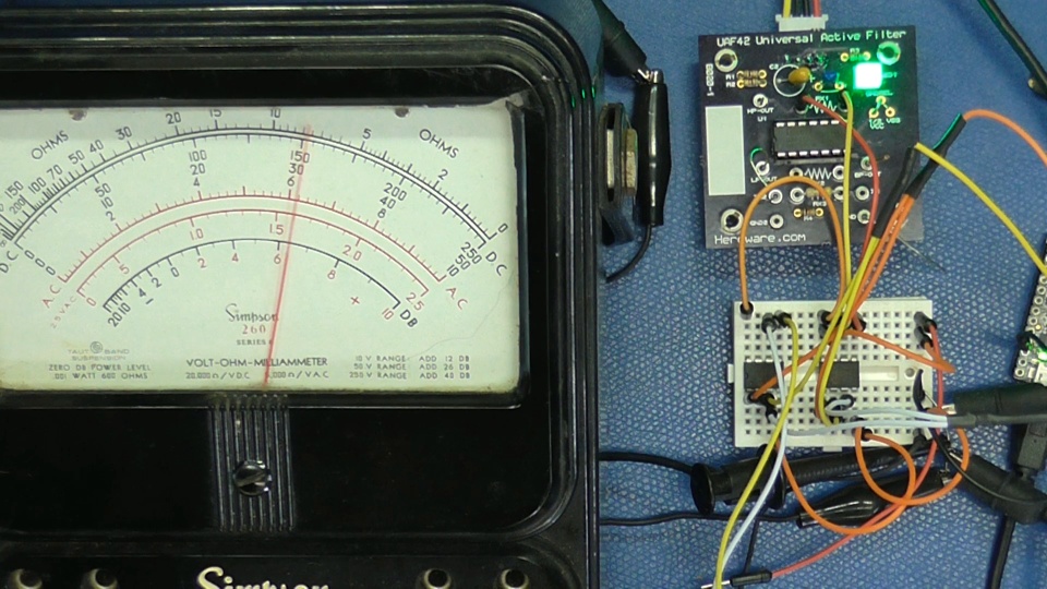
Finally, to visually demonstrate that digitally controlled potentiometer really does emulate a variable resistor I hooked up my old Simpson 260 Volt Ohm Meter (VOM) that I have had since I was 16. Let’s just say that means I have had it for almost 40 years. Setting the VOM to resistance and remembering that Zero ohms is a deflection to the right the effects of the incrementing potentiometer are readily seen.
This was just a simple example of having a processor control our analog project. These days I automatically assume that there will be a serial control bus or two in any sizable project.


The Video is private :/
Great topic BTW. Though I know how this stuff works its always good to learn it again as there often are small details you didn’t know before.
Would be interesting to see mention of more of the issues with dpots “in action” too however — for some reason, they are a part that seems to be overapplied by beginners in really bizarre ways, and people treat them often as if they are “just” potentiometers…for example, isolation is a serious concern depending on where they are in a circuit!
I see that more and more, people blog something, then the video is set private so nobody can see it. sigh
Its happening fast.
You write the article and upload the video but not list it (you want it to come with the article ), then you publish the post and it looks perfect to you. You do not recognize that you also have to make the video public.
No, it’s better than that. Youtube, by some sorcery that I have yet to comprehend, always gets the date wrong for publishing posts.
“Oh, I’d like to schedule this for 07:00 tomorrow”.
“Gotcha, 07:00 on Wednesday.”
It would be interesting to see what the youtube server date-time was. Everyone assumes it’s local but who knows where the physical servers are.
Today is is still Thursday for me, but for much of the world it’s already Friday. I always assumed the world wide web uses the “international date and time”, and the date and time is the same on every sever connected to the internet. Most hams log international contacts in that manner. With troops stationed all over the world I’d guess the US military and others use the international date as well.
Apologies to the author of the above article – I’m sure you put a lot of work into it – but when I encounter a private video in the middle, I stop reading at that point. If it gets fixed, I’ll try and follow along, but in my opinion, critical information necessary to understanding the post is completely missing.
Bear in mind the length limitations of I2C and SPI. There are workarounds but they are shorter than you may think.
Bil,
I’d be interested in hearing your take on I2C troubleshooting. I must admit it’s been hit or miss for me. I’ve redesigned to avoid dealing with the problems sometimes.
I am product manager for I2C devices at NXP. I love debugging customers’ problems. Some are poorly executed I2C chps (both master and slave). Others are bus-level issues (voltages and capacitances). While others are strange interactions caused by the analog nature of the system. 95% of the issues I find are a simple misunderstanding of how the system/parts should play together. The last problem I solved was caused by a slave’s address lines connected to an FPGA which wasn’t driving them to the correct level at power on. The user couldn’t access the slave correctly since it was at a different address than he expected
I just applied for an exploration kit from your company a couple of days ago, we’ll see where that gets me. Most of my problems in the past have been interfacing legacy TWI with I2C slave. Just looking for ways of determining what’s going wrong. I’ve had better luck with TWI to TWI, but the speed limitations have made me rethink that approach more than once. (Good luck on the merger.)
For anything semi-professional with any non-trivial bus (USB, I2C, SPI, basically anything beyond GPIOs) you’ll save a huge amount of time if you have a protocol analyzer. Lots of logic analyzers can decode what they capture, and there are more targeted products which usually have better software decoding (TotalPhase Beagle)
Nothing beats pinpointing the spot where things go wrong. Host isn’t sending the right thing? You’ll see it right away. Slave doesn’t respond? You’ll know where to look..
Always put test points (SCL/SDA/GND at a minimum) and then you can hook up something to look at the signals, with solid reliable electrical connections. You can add the .1″ headers later, but I will start with them included.
I usually just attach the analyzer while I bring thing up, just because I know mistakes will be made and I want to be sure I’m not doing something stupid that will haunt me in the future.
I don’t simply trust people’s libraries or random platform software, because I know how often they’re built without this oversight. You see it even in the most popular things.. someone debugging Raspberry Pi’s support of the CS0/CS1 signal saying “There’s a glitch here, we don’t know why.”
Bil, thanks for this video. I really enjoyed watching.
I found a typo: The SPI MOSI line is labeled “MOSO” on the comparison picture. I actually like that, a line where everyone can dump their thoughts and no one needs to listen. I need this for meetings :D
Remember to mention Paul at Dorkbot’s post on “3 steps to good SPI bus design”: http://www.dorkbotpdx.org/blog/paul/better_spi_bus_design_in_3_steps
This series is great stuff Bil – I’m currently trying to learn a lot about digital control of analogue and filters in particular for synth design and this is exactly the sort of stuff I need to know about. Thanks!
I’ve been wondering about digital potentiometers… maybe Bil or someone else here can answer a question for me. How does a digital pot actually change its resistance? Presumably it’s some sort of resistor ladder, but how does the switching element work? If it were a semiconductor based switch wouldn’t there be a voltage drop? Thanks in advance!
I’m only a hamgineer. I’d approach it from the point, this about emulating a resistor, one function of a resistor is to control the amount of current flowing in a circuit. A pulse width modulated transistor could do that. Two transistors could emulate a potentiometer . Then again I could be way off base too.
But then a base->emitter current would need to flow to turn the transistor on, and there would be a voltage drop regardless of what current is flowing. Wouldn’t that mess up circuits that are assuming it’s behaves like a resistor?
Digital pot is actually MOSFET switched resistor ladder. The same principle is beeing used in DAC (Digital to Analog converters).
Property of a MOSFET is quite different from the bipolar (PNP or NPN) transistor – drain/source channel acts as a resistor, so voltage drop is proportional to the current flowing through. If (as actually is the case) that resistance is much smaller then the resistors in the ladder, so the “numerical error” is very small.
Just as a curiosity, there are MOSFETs with Drain/Source resistance (Rds) in single digit mOhms (1/1000 of Ohm), but those are usually power MOSFETs.
That makes sense. Thank you, Miroslav!
PWM can not be used here – PWM acts as a “potentiometer” only when applied to a “slow” device. For example, one can dim a light (incandescent or LED) using PWM, but only when incorporated with slow response “deficiencies” of a human eye.
If you use PWM on a LED, and measure the effect (“light sensor” connected to a scope), you will see light turning on and off, and won’t see a constant light level changed as your brain registered.
In other word, only “average” value of PWM controlled signal changes, the actual values are zero or max, and that won;t work for (most) digital pot implementations.
Digital filter used here “counts” on constant R value set by the pot, not the average value.
Here is example:
You want filter “centered” at 1kHz. Let’s say that requires R value of 10kOhm. You use PWM that “emulates” 0 Ohm (when on) and 100kOhm when off. By having PWM provide 90% on state (for example 9 usec on, 1 usec off), you might think it’s equivalent of 10kOhm in average, but for filter it’s still 9 usec with 100k and 1 usec with 0 Ohm.
Even if your PWM works an much higher frequency then your central frequency, it won’t work, but the math to explain get’s much more complicated as it includes bandwidth of the active components, plus sampling theory, plus non linear response, plus much much more.
On the other side, when you use PWM on LED, and have PWM change the state at least 50 times a second (preferably much more), your eye and brain average high and low light levels based on their duration.
If you use incandescent light bulb, that integration (creation of the average value) happens due to the slow response of the filament – it cant cool and heat quickly enough to fully turn on and off following the PWM.
Hope this helps :)
Hate to say this, but Bil makes me feel like i’m about to get murdered/gored/kidnapped whenever I see him glaring at me from a banner. Please change that picture, it’s just creepy. When it’s coupled with an overly pretentious/menacing title like “we assume control” I just don’t want to click on it.
Pretty sure I2C is Inter-Integrated Circuit.