[DainBramage] needed a DC ammeter to check how long his amateur radio station would be able to stay powered on battery backup power. The one’s he already had on hand were a Clamp Meter, which could only measure AC, and another one that measured just a few milliamps. Since he didn’t have one which could measure up to 25A, he decided to build his own DIY DC Ammeter with parts scavenged from his parts bin. Measuring DC current is not too difficult. Pass the current to be measured through a precision resistor, and measure the voltage drop across it using a sensitive voltmeter.
I = V/R
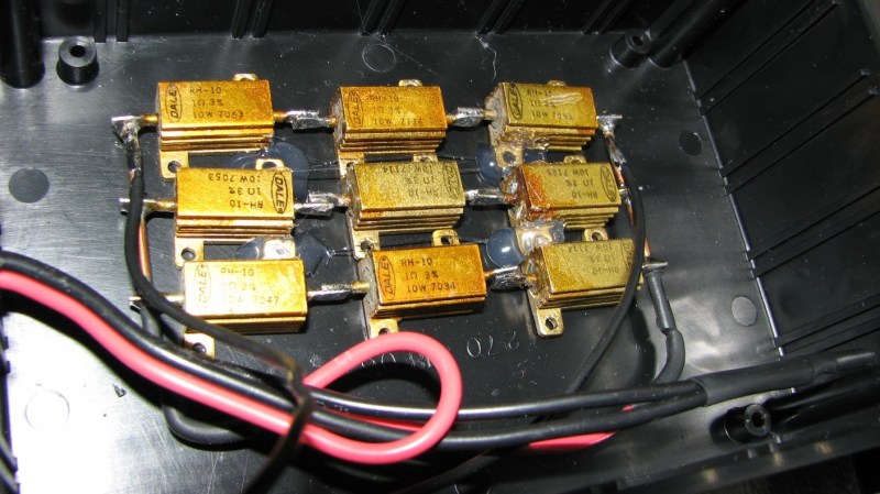
So far, so good. If it’s late at night and you’ve had a lot of coffee, busy building your DC ammeter, things could head south soon. [DainBramage]’s first step was to build a suitable Shunt. He had a lot of old, 1Ω, 10W resistors lying around. He made a series-parallel combination using nine of them to create a hefty 1Ω, 90W shunt (well, 0.999999999 Ohms if you want to be picky). This gave him a nice 1 Volt per Amp ratio, making it easy to do his measurements.
Next step was to hook up the shunt to a suitable voltmeter. Luckily, he had a Micronta voltmeter lying around, ripped out from a Radio Shack product. Since he didn’t have the voltmeter data, he hooked up a 10k resistor across the meter inputs, and slowly increased the voltage applied to the meter. At 260mV, the needle touched full-scale and the voltage across the inputs of the voltmeter was 33mV. [DainBramage] then describes the math he used to calculate the resistors he would need to have a 10A and a 25A measurement range. He misses his chance to catch the fail. His project log then describes some of the boring details of putting all this together inside a case and wrapping it all up.
A while later, his updates crop up. First thing he probably realized was that he needed more accurate readings, so he added connectors to allow attaching a more accurate voltmeter instead of the analog Micronta. At this point, he still didn’t catch the fail although it’s staring him straight in the face.
His head scratching moment comes when he tries to connect his home made ammeter in series with the 12V DC power supply to his amateur radio station. Every time he tries to transmit (which is when the Radio is drawing some current), the Radio shuts off. If you still haven’t spotted the fail, try figuring out how much voltage gets dropped across the 1Ω shunt resistor when the current is 1A and when it is 5A or more.


not only that, but hot snotting those resistors to a plastic casing ?????
Yeah, not sure why he used hot snot when it was going to melt into one molten mess. ;-)
Nope. Test temps never exceeded 120F.
Wirewound resistors also have inductance.
They are only good for measuring true DC.
Yup. No AC in sight. The Astron RS-35M puts out nice, low ripple DC.
In this case, probably okay, depends if the load has switching noise
73
Fail of the week….. Someone trusts his calculator when it says 0.999999… That’s 1/3*3. That should be about 1 accurate to about 1/googolplex.
0.999… isn’t about 1, it *is* one.
Don’t believe me? Look at it this way:
-If 1 and .999… are different numbers, there must be a non-zero difference between them.
-The difference between the two would logically be .000…0001
-Written as a fraction, this is the same as 1/∞
-Anything finite divided by infinity is *precisely* 0
Not precisely. Infinity is not a number, but a property of a series or function. .999 repeating approaches 1 but never touches it, but for many practical purposes can be considered within tolerance for considering it equivalent. But it still is not equal to one.
.999 repeating is the limit of (1-epsilon) as epsilon goes to 0. It really, really is 1. It’s mathematically provable. Just google “999 repeating” – the Wiki article first linked has a ton of proofs on it.
The cleverest one I’ve ever seen involves multiplying it by 10, and you can quickly solve to find that it really, really is 1.
“quickly solve” is bit vague. The thing goes basically like mark for simplicity X=0.99999.., now take (10*X) – X, which is… 9, since the repeating 9’s cancel each other out. But this is the same as 9*X, therefore 9*X = 9 and thus 0.999999… = 1. This is not only the cleverest, but it is also how it was taught at introductory courses at university.
Yeah, your right. I was thinking about it more from the point of view of the calculator, that the .999 was just precision error. But if you solved it out the way the calculator does, you would find your self defining the calculation as a series of repeated steps that could be represented as a series of limit 1, therefore 1.
“now take (10*X)”
The common objection to that is that multiplying by ten is simply moving the decimal point, so there’s now one less “9” on the right side of it, and therefore 10X – X is not 9 but 8.999…1 for any number of 9s you have after the decimal point, including infinite number of 9s, and the proof is invalid.
The idea that the “repeating 9s cancel” is begging the question that 10X – X is necessarily 9 which is a logical fallacy because you haven’t proven it.
The problem is, that if 10X – X was 9 because the part right of the decimal point stays the same, then you must also argue that 10 * 0.1 = 1.1
Or, to illustrate the fallacy in more words:
10*0.999… – 0.999… = 9 = 9X
This is arguing that the infinitely long decimal part of 10*0.999… is equal to the infinitely long decimal part of 0.999… which is a hidden and unproven assumption that isn’t necessarily true. And it isn’t true.
There are different “sizes” of infinity, and it must be so. For example, there are an infinite number of even numbers just as there are numbers, but obviously these are not the same infinity. The size or of the set of even numbers is infinite, but it is still smaller than the set of all numbers, which is also infinite. They have different “cardinalities” of infinity.
In the same way, 10*0.999… must have a smaller set of nines after the decimal point even if there are an infinite number of them.
10*X – 9 < X holds true for any number in the set 0.9, 0.99, 0.999, 0.9999, … all the way up to infinite nines or 0.999…
If this wasn't so, when we multiply 10 * 0.999… an extra +9/10^n has to appear from nowhere, and this number must be greater than zero, but if we set n=inf it becomes exactly zero. There's no way you can make it work.
So, as long as we take 0.999… to be an infinite string of nines, as the decimal notation suggests, it is not equal to 1. Of course we may arbitrarily define it to mean 1, but that's just an abuse of the decimal notation and trying to "prove" it mathematically is just folly.
This is going to blow your mind.
Guess what ∞ – 1 is ?
It’s still ∞ !
Yes, ∞-1=∞. And no, you can’t subtract ∞ from both sides of the equation, that’s not how infinity works.
If the “10*x” bit bothers you, the proof from Euler is also over at Wikipedia, where you can formally define 0.9999… repeating at (9*(1/10) + 9*(1/100) + 9*(1/1000) ….) , or 9 times an geometric series with r=(1/10). Since an infinite geometric series sums to r/(1-r), you get 9 * (1/9), or 1.
Dr. Cantor (posting here as Dax) is correct. I award him aleph(null) internets.
“This is arguing that the infinitely long decimal part of 10*0.999… is equal to the infinitely long decimal part of 0.999… ”
That’s not an assumption. If you define 0.999… as (9*sum(n=0,n=inf.) ( 1/10^n)), then yes, they *do* equal each other, by definition. Multiply that series by 10, factor out a (1/10) from the whole thing, and you get 9*sum(n=0,n=inf-1)(1/10^-n), and “infinity – 1” = “infinity” (the two series have the same cardinality), so the two series are equal.
The ‘different sizes’ of infinity relate to how you can make a map from one infinite set to another one. These “two infinities” have the same cardinality: for every “9” in the first decimal part, there’s a “9” in the second decimal part
“and “infinity – 1″ = “infinity” (the two series have the same cardinality), so the two series are equal.”
No. That is the unsupported assumption.
a – 1 =/= a
This remains true for every a, including a = inf
Therefore the two sets, while both are infinite, cannot be the same infinite, and subtracting one from the other to arrive at zero makes no sense.
a – b = 0 only if a = b.
If a = inf and b = inf – 1 the result is undefined because they are not the same infinity. If this wasn’t so, if we did indeed claim that they are both the same infinity, and that infinities can be meaningfully subtracted like real numbers to make the original argument where the nines cancel out, we would have to conclude that:
inf – (inf – 1) = 0
inf – inf + 1 = 0
1 = 0
So you see, the whole “proof” rests on contradictions and semantic confusion over what infinity means.
There has to be a *mapping* from “a-1” to “a” for them to be the same cardinality. And that of course works: for every element in x=(1,infinity) there’s an element in a=(0, infinity), with the mapping “x=a-1”. The set of real numbers from 0 to infinity maps to the set of 1 to infinity fine.
There are lots of other examples: for instance, the set of all integers is the same cardinality as the set of natural numbers (Z and N, respectively). That is, (-infinity, +infinity) is the same cardinality as (1, infinity). Even the set of all *even* natural integers is the same cardinality as the set of all integers.
“Infinity” is not a number, so claiming that there are “different infinities” makes no sense. There are infinite *sets*, and those sets can have different cardinalities. But these *do not*. Here you have two sets of repeating 9s, and there is a 1-to-1 mapping between them, so they have the same cardinality. This is very well-established set theory.
.9 repeating *is* equal to one. .999999999, on a calculator may or may not be equal to one.
the problem here is conflating a mathematical identity (i.e. 1/3 + 1/3 + 1/3 = 1 = .3333… + .3333… + .3333… = .9999…) with a limited precision readout.
Dax, While you are correct that there are different infinities, you are misguided here. For instance, while it is mathematically possible to map the numbers between -1 and 1 to the set of all real numbers (this makes them the same infinity) you can not map the set of integers to the set of real numbers. In this case 0.99 repeating will always be the same decimal no matter how many shift operations you do. This is because an infinite list of 9’s is infinite, and a shift does not change this type of infinity. However, congrats on forcing me to recall my discrete math course.
” In this case 0.99 repeating will always be the same decimal no matter how many shift operations you do.”
Alright, if this is so then 1/10^n must equal 1/10^(n-1)
The definition of 0.999…. is the sum of 9 * 1/10^n where n goes from 1 to infinity, which results in a sum:
0.9 + 0.99 + 0.999 + … + 9 * 1/10^n
Multiplying that by 10 results in:
9 + 0.9 + 0.99 + … + 9 * 1/10^n-1
So, we subtract the nine, and argue that the resulting sum is the same as the one we started with, therefore their last terms must be equal:
1/10^n = 1/10^(n-1)
n = n – 1
1 = 0
Contradiction.
The confusion comes from the fact that “infinity” isn’t a number.
If a = inf and b = inf we cannot say that a – b = 0 because we haven’t explicitly defined that a = b.
Therefore we can’t say that 10^inf = 10^(inf – 1) because we haven’t defined how large those infinities are relative to one another. Therefore we cannot say that 0.999… = 1
The fallacy of 0.999 = 1 is a kind of like saying that if we shoot off two photons into space, one after the other giving one a 1 meter head start, they should meet up after travelling an infinite distance because the difference between them relative to the distance they have travelled tends to zero, or has a limit at zero.
But they won’t. They will always be separated by a meter no matter how long they go.
It is very difficult to concieve how or why you could use the decimal notation to represent a number that has exactly zero difference to 1 except by writing down 1. It is in fact impossible.
“It is very difficult to concieve how or why you could use the decimal notation to represent a number that has exactly zero difference to 1”
It’s not your choice. It’s the way the real number system works.
If you don’t want it to work that way, there are other systems you can use (like p-adic numbers, non-standard analysis, etc.) but then *other* things happen. You can’t just say “no, 0.999… is not 1” and expect it to have no consequences. It does.
For instance, if 0.999… is not 1, then the sum of the geometric series (1/r)^n , for r > 1, cannot equal (r/(1-r)). That’s Euler’s proof, and it has no “different infinities” at all. It’s straightforward. 0.999… = (9/10) + (9/10^2) + (9/10^3)+… , or 9 * geometric series for r=10, and the geometric series for r=10 is equal to (1/9)… so it’s equal to 1. In fact, if 0.999… is not 1, then *no* infinite series converge to exact sums, which ends up being the basis for a lot of proofs in calculus.
Or, to use the quote from Gowers, in the Wiki article, choosing 0.999.. to be 1 is a convention, “[h]owever, it is by no means an arbitrary convention, because not adopting it forces one either to invent strange new objects or to abandon some of the familiar rules of arithmetic.” Fundamentally, it’s the Archimedean property of real numbers. If you don’t like it, then you’re forced to use a number system that’s non-Archimedean. That’s the way it works.
So why would you choose to have a decimal representation of a number that has exactly 0 difference to 1, but isn’t 1? Because it makes calculus, and a lot of other mathematics, work.
Quote: “If you don’t like it, then you’re forced to use a number system that’s non-Archimedean”
1/3 + 1/3 + 1/3 = 1
Nah, definitely too hard to use a non-Archimedean system for me.
Which is another consequence of 0.999… not equaling 1: repeating decimals could no longer be rational, or 0.333… is no longer equal to (1/3). there’s no way around this, it just uses the same geometric series sum as the Euler proof.
There’s a reason why math is complicated.
A repetitive number (i.e. 0.55555….) can be represented as a fraction: 5/9 (the rule is simple, 0.454545 = 45/99, 0.333333 = 3/9 etc…). Therefore 0.999999 = 9/9 = 1
SHEEEESH!!!
All this squawking about whether my shunt was 1Ω or 0.99999999…Ω! I’m here to tell everyone:
IT WAS ONE OHM EXACTLY!!!
I measured it! Using two different meters!
With a group of 1 ohm, 1% resistors connected this way and given the accuracy of a typical 4.5 digit meter likely will not be able to tell if it is 1 ohm or 0.9999999…. ohm, for practical purposes it is 1 ohm.
For large values of 1, 1 approximates 2 for small values of 2….
-1
At the risk of getting into an infinitely long argument … none of this matters anyway.
To posed problem was a series / parallel net work of nine resistors.
The calculation is … r = 1 / ( 1/(1+1+1)^2 + 1/(1+1+1)^2 + 1/(1+1+1)^2 ) / 3
This evaluates to … r = 1 / (( 1/9 + 1/9 + 1/9 ) / 3)
At this point some are calling this a precision error. It is *not* a precision error because your calculator can deal with the numbers ‘1’, ‘3’ and ‘9’.
It is because you are entering a maths problem into a calculator and not a root equation.
If you simplify the equation to it’s correct root you find r = 1/1 and if you enter that into your calculator it gives the correct result.
Put simply, a calculator cannot deal with a number below a vinculum (denominator) that has a prime factor (excluding 1).
To say 0.999… is equal to 1 is rubbish, 0.999… is a failed mathematical attempt to define ‘1’ in decimal notation through an errant process. If the value ‘1’ has the definition ‘1’ then it cannot have a second definition ‘0.999…’ If you think it can then look up the meaning of definition.
Fair enough there are ‘approximations of increasing accuracy’ but the word ‘approximation’ does mean ‘equal to’.
Infinity is 1 / 0 and that is it’s only definition. It does not have a definition in decimal notation because it can only exist in algebra. Anything expressed in decimal notation is an approximation.
Think of ‘1’ as being 1 * 1 to the base 10 and to the exponent 1. Now you know the base doesn’t have to be 10, we have binary right? You know the exponent doesn’t have to be an integer in math. Well get this, the base doesn’t have to be an integer either. It could PI (or even PI squared) and a lot of times that can be very useful. So the argument here is about a poorly chosen base (base 10) for some math when in fact the base is completely arbitrary. Unfortunately your calculator is stuck in the world of base 10.
“…prime factor (excluding 1).”
I think you mean 2. Calculators use base-2 floating point representations (generally), therefore they have no problem exactly representing, for example, 1/2, 3/8, 17/256, etc. (up to a maximum precision) Also, 1 is not prime.
“Anything expressed in decimal notation is an approximation.”
No. This is only true when doing calculations on measurements using significant digits as a rough indicator accuracy, or when rounding, using irrational numbers, etc.
The ampermeter doesn’t work, but it has nice hackaday.io sticker.
Except of the few fail levels mentioned above, those resistors usually don’t have good temperature stability, resulting ib measurement error once it gets warm by power loss on it. Especially when it is hot-glued to plastic… those resistors are meant to be mounted on metallic radiator. They will not dissipate all the watts printed on them without it.
Oh yes, and the adjustment screw https://hackaday.io/project/4483/gallery#a9d40dd501bb59ec86ca368f860be74f isn’t meant to be covered.
looks at the needle offset and facepalms …
I think that picture explains a lot about this epic fail.
The needle zeros perfectly when the meter is resting vertically, which is the orientation I use it in. Also, since the analog meter will only ever be used for ballpark measurements, zeroing isn’t important.
Well, 1Ohm shunt to measure 25 amps, whoa … Even a cheap supermarket meters have smaller burden voltage than that!
And the entire thing didn’t melt into a plastic blob only because the radio shut off. He seriously wants to run that hotglued in a plastic case?!
I boggles my mind how a ham radio operator can fail so badly on basic electronics :( When I was doing my exam, basic electronics (along with first aid and safety around electric devices) was a part of it, but perhaps different country different rules …
eehh Jan, ….. 1 Ohm? 73 on4ndo
ok blind hamradio operator :-P… sorry O 0 ……
Yep, basic electronics were included in both the Technician and General level tests that I aced (in the same sitting), and some more advanced electronics were included in the Amateur Extra test that I also aced.
I’m not an idiot, I made a mistake. I forgot ONE thing, the voltage drop across the shunt.
As for the temperature of the shunt? it never even got warm enough to soften the hot glue.
But as neither of you have ever made any mistakes, I bow to your obvious perfection.
Every one of us made those, and dumber mistakes, but not everyone will own up to them :) It takes spheroids. I tip my hat to you.
Thank you kindly, Miroslav.
Mistakes are learning moments! Remembered for the next time (5-10years) you have to roll your own shunt. But if your like me, 5-10 years later you can forget you made that mistake before and do it again!
Hm. It’s kind of … well … obvious. Still that’s a perfectly fine mistake because eventually he’ll always remember how to properly calculate a voltage drop… But it took me 3 Minutes to get what you’re talking (writing) about.
Btw: I = V/R is : Units of measturement vs. symbols! It’s I=U/R with the units A V and Ohm
That’s perfectly fine, never heard the phrase “In God We Trvst”? *grin*
It’s just an older Latin transcription of Ohm law.
I accept V as my Symbol of Voltages.
I accept U as my Symbol of Voltages.
Ok, thank’s! Learned something new today. Kind of embarrassing as I should know …
“A little known cause of the fall of the Roman Empire was the introduction of the “U” in their canonized system of electrical engineering. The original V, taken from the Greek philosopher Ohmicles carried them through the expansion from Gaul to Mesopotamia but when the U symbol entered picture, the confusion, when added to digital meters reading in Roman numerals and the attendant problems with exponents caused the massive electrical fires in Rome during the reign of Nero.”
(Yost Makinitup – History of Electrical Engineering in The Roman Empire, MCMLVII)
http://web.mit.edu/smaurer/www/blog/051022%20story/77.JPG
You’re nuts, N V T S nuts …
It’s gonna take a Miracle to get out of this one…
5 points for the movie reference.
Hmm, you may just have hit upon a regional difference or something like that. All of my physics books used I = V/R for the symbols.
My EE college textbooks (from before I switched to CS) say I=E/R, where E is voltage. When or where did we switch from E to U and V?
E= Electromotive Force, which is measured in Volts.
Every analog meter I’ve come across (and as a former TMDE guy, that’s quite a few) has a full scale sensitivity current rating. Usually this is listed somewhere on the meter as ‘ohms per volt’ or ‘ohms/volt’. What this means is that for a full scale reading, you need X amps (usually milli or micro) to swing the movement to full scale.
It should be a simple calculation then to calculate the shunt value required to measure 25A DC. If you have a 50uA meter movement, then you need to sink 24.99995A across the shunt, which should be in a parallel circuit with the meter movement.
i always understood that engineers use different symbols from technicians.
E = electromotive force = voltage = v
never seen U before
In their SI definitions,
E = electric field [V/m] or [J/C/m]
V = potential difference [V] or [J/C]
U = potential energy of a test charge = qV [J]
U = V when the test charge is defined to be 1
V is safest. U and E are used for other physical things that also show up in an electric circuit. V is just shared with volume, so it’s not likely to be confused.
In physics, there are some people who consider something like “voltage” to be ‘low-brow’ (in the typical, we’re better than you engineers theoretical physicist kind of way) because it’s “-age” stuck on the end of the measurement unit, just like “amperage” for current, “grammage”/”poundage” for weight/mass, “wattage” for power, or “ohmage” for resistance. And so “electric potential” gets used. The more practical ones, like me, say “electric potential is two words, voltage is one word, so shut up.”
Using electric potential also confuses it with potential energy, which classically uses “U” as its symbol. Using ‘U’ for voltage just further confuses things.Sooo many students get tripped up by “electric potential” sounding like “potential energy.”
For ‘E’, it should be “curly E”, not E. E is classically electric field. Curly E is emf (“electromotive force”). emf is more like a *kind* of voltage – one that exists separate of the connections in the circuit itself, like a battery. The problem is that ‘curly E’ isn’t on a keyboard, so it’s too easy to confuse it with electric field. Again, way too many students get tripped up because of that, and to me, it’s an esoteric difference anyway so I don’t really see the point.
Voltage is actually a potential difference and hence the ‘U’. However ‘U’ is more related to coulombs than electronics. Technically it is totally incorrect to use ‘U’ for electronics because electronics is based on conventional current flow which opposite in polarity to coulombs of charge. The ‘V’ is quite implicitly reversed in current flow to ‘U’. Atomicity, ‘V’ is proportional to the number of electrons an atom is missing below it’s valence point while ‘U’ is proportional to the the number of additional electrons above an atoms valence point.
Script E – Unicode #8496: ℰ
U is classically used for potential energy. See thermodynamics, basic classical mechanics… just about anything. Anywhere you find potential energy, you’ll tend to find ‘U’. Voltage is an *electric potential* difference. That’s not potential energy – it’s potential energy per unit charge, or joules/coulomb. That’s why it’s really, really confusing to use ‘U’ for voltage, because it makes it look like a potential energy, when it’s not.
The rest, where you’re talking about electrons above/below… makes no sense. Atoms have nothing to do with voltage: totally free electrons generate an electric field, and a voltage. Voltage is a potential difference. It’s *energy per unit charge*. It doesn’t care whether or not that charge is positive or negative, at all. If the charge is negative, then the change in energy across that potential is negative. That’s all. If I have a 12V battery, and I hook up that 12V battery to two big metal plates in a vacuum, an electron will go from the ‘0V’ plate to the ‘+12V’ plate and gain 12 eV of energy. (Or equivalently, it takes 12 eV of energy to pull an electron from the 12V plate to the 0V plate). If I put a *proton* in that vacuum, it will go from the 12V plate to the 0V plate, and gain 12 eV.
‘U’ is used in Europe, where it’s equal to what V is used for in the US. There’s some bit of distinction there where ‘U’ is actually a potential difference (i.e. U = V1-V2) but that’s silly, as ‘absolute’ voltage is a convention rather than something fundamental. The argument against using V is that “V” is used for the unit, so it’s confusing – I don’t find this argument as convincing as avoiding confusion with potential energy. I guess what this all means is that no one has a good symbol for voltage.
Wow. So much attemtion for a small thing. It’s – as I read on wikipedia – a difference between between Anglo-American and European. I am german, I only saw U before. However eventulally you’re free to change symbols. Like we used j instead of i for imaginary numbers so there’s no confusion with time dependant ac-currents i.
In my part of the World, it’s always been I=V/R, hence.
I relate the use of “U” as more Europe centric, just like using the comma instead of dot for decimal mark. Regional differences, as someone commented below.
Never saw U as voltage used here in my Belgium electronics books/courses.
But that might have changed the last 20 years… :)
Former Yugoslavia republics use U, with V as a reserve when dealing with american schematics :D
As I can track it down, comes from German literature…
You’re correct, Christoph. I will probably never make the same mistake again.
I would have used a bit of fencing wire or a nail. Trim the wires resistance with a file while using 1% resistors in a Wheatstone bridge to calibrate. Then measure with a digital meter on the lowest mV range.
As a defense for Anool:
> I = V/R
can actually be used like that. Yes, using U for voltage is more common, but V is still seen at times.
That being said,
> He made a series-parallel combination using nine of them to create a hefty 1Ω, 90W shunt (well, 0.999999999 Ohms if you want to be picky).
Is really really really bad. It shows that whoever cross-read that text has had as little *understanding* of the principle involved. I don’t even know how one would get to that number. Seriously, who would use his calculator to calculate the resistance of three parallel resistors of the same (1+1+1)Ω=3Ω resistance? Insane.
I urge hackaday, which is more and more becoming an editorial magazine, to actually enforce a four-eyes principle on articles. It does wonders.
Oh by the way, the first fail was to ignore his Fluke clamp “because obviously, it won’t work on DC”; it works perfectly fine on DC. I don’t see a reason it should not — it’s the same as it’s smaller brother, the Fluke 321, but the Fluke 322 is able to measure DC; that’s the cool thing about it, and probably the cause why someone spent the additional amount for that.
The fail is yours. :) The Fluke 322 provides DC *voltage* measurement, not DC amperage.
All the fluke meters can measure DC current if you obtain the AC/DC Current Clamp accessory, which contains a hall-effect sensor:
http://en-us.fluke.com/products/all-accessories/fluke-i1010.html
Or this:
http://www.sears.com/extech-400a-ac-dc-current-clamp-adaptor-w-ncv/p-03416274000P
DIY is not always the best value.
Clearly it is in this case. The cost of the Fluke AC/DC add-on clamp is twice what I paid for the 116 and 322 together!
DIY is a much better value, especially when you take the fact that I have corrected my error and now have a functional and accurate ammeter into account.
The Fluke I1010 is over $300!
I wonder if there’s a way to mark a statement as being made “tongue-in-cheek” ? I tried brackets, but obviously it didn’t work.
:) smiley’s work ?
The math tells us it will be 1 ohm, but some calculators “think” otherwise and return 0.999999999 !
point is that you shouldn’t be editing on hackaday.com if you don’t understand that. I don’t think that Anool had an ironic intent when writing it like this, but I’d totally love to be proven wrong.
Don’t worry about it, Anool. You can’t please everyone.
Truthfully, when I made the shunt I was pretty much ignoring the math. I knew that 3 1Ω resistors in series would be 3Ω, and three 3Ω resistors in parallel would be roughly 1Ω. That’s the limit of the math I did. I just adjusted the wire lengths while checking the overall resistance until it read 1.0Ω. I didn’t care about precision beyond 1 decimal point as this was never intended to be a precision meter.
lol. I didn’t pay attention to that. I just noticed it was different to the theoretical resistance and assumed it was a measured resistance but too may decimal places for that. So someone did the whole 1 / R^2 thing with 3 ohms ie 1 / 3^2 = 1 / 9 = 0.1111111111111 lol
Power resistors of this rating are typically wirewound. Depending on how they’re wound, they may have significant inductance. So for each large load step, you get a nice little voltage dip/spike as well.
If you are expecting to tap off up to 90 watts, then would be measuring the power of a broadcaster.
Free way to do it. Just measure the milivolt drop across any decent length of wiring from the power supply. Use a known load to calibrate. Get calculator out.
I have long known that a milliohm range is what is needed here, I would have paralleled all the resistors.
I have a few digital panel meters to use in another bench power supply project.
A 2 volt full range meter needs a times 10 or 100 amp gain to work with a drop resistor that is a low burden.
Actually, this comment here is excellent. Not only do you get a “free” measure of current, but you are also monitoring something that you care about (voltage to your radio). As the original experimenter found out, adequate voltage to your radio is essential.
Note also the resistors are 3% tolerance, 0.999999999999 Ohms indeed? Somewhere between 0.97 and 1.03 Ohms.
so what, any good meter is 1% or better. Measure the resistance and use that in your calculations.
The accuracy of the meter only comes into play after the tolerance of the resistor.
The tolerance of a resistor includes the T/C, or temperature coefficient. That is, within normal operating temperature the resistor is expected to stay within 3% of it’s tolerance (taking into consideration the built in tolerance, and the resistance of the connections). If you can calibrate the resistor at a specific temperature, and keep it at that temperature during it’s operation, then the resistor will stay very close to that calibrated value (ignoring inductance/reactance). But since these resistors are dissipating so much heat, then the value will change according to the T/C.
It’s better to choose a high tolerance resistor with a low T/C, and overrate that resistor so it stays well within the normal operating range. The higher the wattage, the less effect T/C will have from self heating, excluding ambient temperature changes. This means that your calibrated resistance will be closer to the in-use resistance.
The best way to calibrate is by using a high precision current source or a micro-ohm meter.
To make this sort of measurement within the realms of accuracy you are implying, you can’t just measure this with a standard DMM/’any good meter’, it would require a 4-wire measurement setup. The probe wire resistance and contact pressure will significantly influence the readout otherwise.
The meter is measuring voltage during operation, not resistance. Effectively, you *are* using a four-wire Kelvin connection – the power supply/load connections are the primary terminals, and the DMM leads are the signal terminals.
Nope. 1.0Ω right on the dot.
http://www.allegromicro.com/de-DE/Products/Current-Sensor-ICs/Zero-To-Fifty-Amp-Integrated-Conductor-Sensor-ICs/ACS712.aspx
This, and I wish I could make it bigger. If you want to make your own ammeter for a *large* current, the integrated Hall effect sensors are great, and they’re like, 2 bucks on eBay.
I remember doing my electronics degree that the square root of -1 was “j” in half of my lectures and “i” in the other half. How we laughed.
P=RI²
Ok so for all us noobs what was the problem?
its pretty much a math fail. i think the article intended to show the wrong math intentionally to get people to think about it, say ‘that aint right’, then do the math yourself and figure out why its wrong. but most of the people who read this dont have time for such intellectual wankery. you can even call it a fail in its own right.
The voltage drop is exactly as high as the current when using a 1Ohm resistor. So at 5A the voltage drop is 5V causing too low voltage at the radio which will in turn shut down.
Thanks for X-plaining this!
Basically, everything that could be done wrong, was. Everything that was done done wrong, was done again, usually incorrectly.
You need a series sense resistor the doesn’t affect the output voltage too much, yet still produces a large enough voltage drop to be usable. Towards the end of his blog, he was using a 0.05 Ohm 5 Watt resistor. As he found, a 10A current produced a 0.5V signal.
Bare meter movements respond to current, not voltage, often in the range of 50uA to 1000uA with low resistance (<100 Ohms). You make them sense voltage with a series resistor that limits current through the meter movement. Better meters take the resistance of the movement into account, but the movement resistance is very small compared to the current limit resistor.
With a 0.5V source voltage, find the series resistance that makes the movement go to full-scale. Connect the resulting "0-0.5V voltmeter" across the 0.05 Ohm current sense resistor. You now have a 0-10Amp ammeter.
Thanks. Very kind of you to be so viciously clear about everything that I screwed up.
I’m sorry you feel that way – it wasn’t aimed at you… but I understand how it could have been read that way.
Rather, I was responding to the question “what went wrong?” Rather than go into detail what you did wrong, I described how you would do it right, and let the reader see the differences.
But if you’d rather I critique what YOU did wrong, here goes…
1) …
On second thought, I don’t really want to embarrass you any more than you have been.
You entirely failed to embarrass me. I did however, get a good laugh out of comment #5 on your PM.
Technically, the source voltage is no longer 0.5 V when you add the meter to it. Diverting 50 uA past the shunt and through the meter will reduce the voltage to 0.4999975 Volts.
This wouldn’t really matter here, but if you’re trying to use a meter designed for 1 Amps to read 10 Amps with an external shunt, or if you were trying to meter smaller currents in the range of milliamps, assuming that the meter doesn’t affect the source voltage means your needle will never rise to the top.
the fail here is not paying attention in class
in my class we were taught to put a voltmeter across the load when measuring current, because usually it’s the power dissipation you’re after, and you need the voltage across the load to calculate it. in this case the user would have said “where is my voltage” right away.
The load under normal conditions would see the full voltage of the power supply. it is fruitless to measure the voltage of the load in most conditions, as it’s the power supply’s job to keep a steady voltage. If you measured the load at the input, and the power supply at the output, you would only see a tiny drop in voltage attributed to losses in the power transmission wires. assuming that properly rated wires were used, this drop should be negligible.
Stephanie gets it.
When I’m powering a radio that draws only 5A with a 35A linear supply, voltage drop is almost immeasurably low. So you introduce a small resistance into the circuit and measure the voltage across that. My mistake was forgetting part of the equation in my hurry to put the ammeter together.
As for “not paying attention in class”, what class? I’m self-taught. I didn’t have the advantage of secondary schooling that many of the people here seem to have. I’m not an engineer, I’m a hobbyist.
Wow, 50 comments before I even knew that my project had been posted!
To clear some things up: I understand Ohm’s law, and have since I was a child. In my hurry to slap together an ammeter which was an accessory to another project I was working on, I forgot to account for the voltage drop across the shunt. For those of us who are not engineers and working on things like this every day, this is an easy mistake to make. Also, I measured the shunt and adjusted it until it was precisely 1Ω, measured with a Fluke 116 and verified with an HP 3457A bench meter.
Many of you have accused me of being uneducated. You’re correct. I’ve learned everything I know about electronics by turning on my soldering iron and making something or fixing something. This is one of those learning experiences. I learned something, and I submitted it as a fail of the week in the hope that someone else can learn from my mistakes as well.
As for hot-snotting the shunt resistors down, I did some testing first. Drawing a 5 amp load through them for 15 seconds resulted in them only getting up to around 120 degrees F. I could still hold them in my hands. Since the measurements I was planning on making were only going to take a second or so, there was no worry that the shunt resistors would overheat. There wasn’t even any danger of the hot-glue melting! If you had read my write-up, you would know that.
Also, since the analog meter was only there to give ballpark measurements, covering the zeroing screw over was intentional. All precise measurements were taken with a Fluke 116 using the meter probe connections.
Lastly, buying a cheap ammeter or an expensive add-on to my Fluke 322 was not going to happen. I built this ammeter out of junk-box parts to take measurements one time, and then maybe keep it around for future use. I didn’t want to spend any money on it, and I didn’t.
Yes, I made some mistakes. I learned from them. Who among us has never done the same?
If nothing else, everyone who reads this, and you, will learn a good lesson. And to be honest, I learned about the voltage drop over a long wire in similar way :)
Hurry and electricity is a big no go.
Huh. Is that true?
15 years as a commercial electrician, and I never knew that. :D
Much respect for your post. You and I went to the same school. I had so many fails as a kid, that I boxed my kit up several times, only to open it again when I got stuck at home for a month a couple of years ago (Thanks HaD, Sparkfun, Adafruit, and the lovely Arduino). I’m not an electrical engineer (I’ve got three other jobs that demand my time), but I’m learning. Learning from other’s mistakes is nicer, and I really appreciate the folks that put their stumbles up for us to learn from. Thanks.
Very kind of you to say. Thanks.
Just spend 20 minutes debugging a power supply I stripped and put back together before I noticed a pesky little plug was only half way in.
Very good reminder I needed to get out to the pub and a beer or 2.
It happens to all of us. Enjoy your evening out. :)
Took me 30 years to get reasonably comfortable with electronics as a hobbyist. To this day I occasionally have to warn my woman “I don’t know what’s gonna happen when I plug this in, so you may hear an explosion and cursing from my shop.” You have cajones for offering up your mistakes for a FoTW.
Thank you. I appreciate that. :)
I often have to issue the same warning to my family members. I am very familiar with the “turn it on and duck” routine. :D
Own it my friend :)
I have been doing this a long time, and still make mistakes. It happens. But I try to laugh it off and own it. No one can put me down if I do it first :)
In haste, I went to view both legs of an h bridge to demo for someone on a scope,so they understood the output, guess what, I put probe tip and ground clip on output and second lead/clip on input signal, poof went the mosfet lol
At least it was the mosfet and not the scope that went poof! That would have made for a much more expensive demonstration.
We all make mistakes. This I know from hard experience. I just wanted to share this one so that others could avoid repeating it. Also, I agree whole-heartedly with what you said about laughing it off. A good sense of humor is more valuable than any amount of skill with a soldering iron.
Have you considered the ACS712x30A which can be found on e-bay for less than a dollar (US). This is a hall effect device which is simply placed over a wire (as a part of a module); therefore, the resistance is about the same as a piece of wire. These can be used with Arduino, Raspberry Pi, PIC, or any computer with a 5 VDC A/D converter. I have make current sensors from short sections of small wire as the resistor (very low resistance) and used amplifiers to get up to discernible values. The ACS712 also comes in a 5A and 20A module (choose which is best for your application (perhaps two could be used in series for better low end resolution if needed). I am a seasoned engineer and an expert in physics, any classical trained engineer would have long ago forgotten any use of “U” with reference to Voltage. I work as a prototype engineer and keep my hot glue gun close for immobilizing wires, components and as an excellent insulator against very high voltages: I would not stop using it. I actually have high temperature glue as well as the common low temperature type. The first cut on any prototype is seldom perfect (and often does not work at all). I would rebuke any expert in my fields which lord over newbies, after all “Ohm’s Law” is a fact, but “The Electron Flow Theory” (upon which it is based) is just that (a theory).
I probably have one of those sensors or something similar in a drawer somewhere here, but I was looking for a quick and simple solution to help with a different project.
I may consider doing what you suggest in the future, it strikes me as a very interesting and useful project to try. Thank you for the suggestions, and thank you for standing up for some of my less popular “engineering practices”. I’ve never used hot glue as a high voltage dielectric, but I might have to give that a try some time (safely, of course).
The discussion of math is interesting…. but there is only a loose connection between math and applied electronics. Anything past a couple decimal places means nothing. The world is not exact. Try to find a resistor with better than 1% tolerance. If you can get resistors with 0.001% tolerance, what about the fact that they change resistance quite a lot based on temperature. I work as an engineer and had an electrical engineering student working for me. Nothing he designed on paper worked. The math worked, but not the circuit. Learning to build electronics with real parts requires theory and some practical horse-sense which comes from experience, which is what you are getting.
As for hot glue as an insulator, you should check out the dielectric strength of polyethylene! It is like 20 to 160 MV/m. Some of the best homemade capacitors are made with plastic film and can withstand many thousands of volts.
The original idea of measuring DC Amps can be done with the ACS7112 module. Two in series should work, one 20 or 30 Amps and one 5 Amps. This gives you good resolution on the low end. They also measure AC Amps. They cost about $1.00 each on e-bay. I have used this type of solution many times. Put a little distance between the two sensors to prevent interaction.
For your project, I do not see extreme precision important.
Also relevant, you can make a clamp sensor using bits from an old UPS.
The part wanted is a small black ring shaped object with two or more wires (careful, fragile) and a hole in the middle where a thicker cable goes through.
I’ve used 4 lead linear Hall sensors from old 5 1/4″ floppy drives and VCR cylinder motors before, these also work.
Made a field meter using one ages ago and this worked very well.
Where are the hall sensor(s) on a 5.25″ Floppy Drive? The 5.25″ FDD had a hole in the disk and an optic sensor.
Did you mean 3.5″ FFD’s because they don’t have an optic hole? I know 5.25: CD ROMs have a Hall sensor on the spindle motor.
I am just curious as the what are good places to find hall sensors.
don’t most ups use current transformers?
You’re thinking about an AC UPS. A simple diode pair is all that’s needed for DC, at least in it’s most simplified form.
Why is it cool to point and laugh at someone’s mistake on a nationally known electronics/maker blog with a segment called “Fail of the Week”? I know this has been around a while, but really, why? I think Hackaday is actually discouraging people who would otherwise get into electronics by publicly mocking people’s “failures”. Yes, Edison “failed” many times and learned from it on his way to making a light bulb that worked, but I’ve always thought the title of this segment was the wrong way to approach an audience intent on learning. Not everybody is going to find this funny. Some may find it very negative. My two cents.
In this case, no harm done. I’m the one who submitted it as a fail. I was hoping that others might be able to learn from my mistakes.
The way you should measure DC current without a voltage drop is to create a “U” shaped half loop of wire or copper and then use a hall effect sensor to measure the intensity of the magnetic field produced.
Good on you DainBramage! You saw a need and dug around in your parts bin for a solution rather than shopping online, that’s why we’re here! Thanks for letting HaD share this little oopsie and don’t let a few loudmouths looking to score imaginary points, with what they hope are witty comments, get to you.
Designing “on the fly” is a sin I routinely commit even though Mr. King drummed the importance of drafting our flowchart BEFORE we hit the keyboard in our high school computer science class so many years ago. That advice applies to anything, especially DIY, and I think about him and that advice every time something like this comes up.
I haven’t forgotten Big G! It’s just sometimes my flowcharts(plans) have the benefit of some recent practical experience… usually in what NOT to do. :)
Thanks, Jeremy. I appreciate your kind words.
My parts bin is extensive and is almost always where I shop first when I need something. Designing on the fly is a good way of describing most of the electronics projects I do. I end up with my share of problems from this, but I also learn quite a bit in the process.
Who would have thought a few resistors would have caused such a stir !
I got a good giggle out of your pain ;-)
Reminded me of some of my not so fantastic ideas – well I’m sure they were at the time. :)
Thanks. I’m glad you were able to see the humor in this, as I was. If we can’t laugh at our mistakes, we are taking life too seriously. At least that’s my opinion.
And I agree with you, this is quite a bit of commotion over a few resistors and a meter. I think it’s hilarious! Some folks here think I’m an imbecile for forgetting something so basic, others think I’m brave for submitting it. I just think I’m a normal guy who makes mistakes. :)
For measuring currents in that kind of range, you use a shunt resistor of 0.1 to 0.01R. (You also attach your volt meter probes directly to the shunt terminals, rather than the PSU terminals, which is a very common noob mistake that ruins accuracy.)