A liquid-fuel rocket engine is just about the hardest thing anyone could ever build. There are considerations for thermodynamics, machining, electronics, material science, and software just to have something that won’t blow up on the test rig. The data to build a liquid engine isn’t easy to find, either: a lot of helpful info is classified or locked up in one of [Elon]’s file cabinets.
[Graham] over at Fubar Labs in New Jersey is working to change this. He’s developing an open source, 3D printed, liquid fuel rocket engine. Right now, it’s not going to fly, but that’s not the point: the first step towards developing a successful rocket is to develop a successful engine, and [Graham] is hard at work making this a reality.
This engine, powered by gaseous oxygen and ethanol, is designed for 3D printing. It’s actually a great use of the technology; SpaceX and NASA have produced 3D printed engine parts using DMLS printers, but [Graham] is using the much cheaper (and available at Shapeways) metal SLS printers to produce his engine. Rocket engines are extremely hard to manufacture with traditional methods, making 3D printing the perfect process for building a rocket engine.
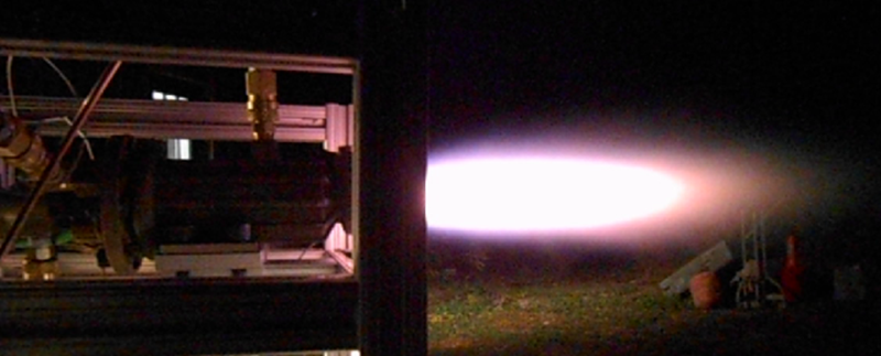
So far, [Graham] has printed the engine, injector, and igniter, all for the purpose of shoving oxygen and ethanol into the combustion chamber, lighting it, and marveling at the Mach cones. You can see a video of that below, but there’s also a few incredible resources on GitHub, the Fubar Labs wiki, and a bunch of pictures and test results here.


Great Project!
I think I’ll leave that one out and build something else.
Correct me if I’m wrong, but are those cooling fins running along the engine or coolant channels? If the former, how well does it help to dissipate the heat from the engine? If the latter, is regenerative cooling being used?
It’s regen cooling.
The cool part about 3D printing this stuff is that weird geometries are easy. I have some plans for a NH3 and N20 engine – machined, mind you – and simply building the engine with a lathe, mill, and welder is really, really hard without a multi-million dollar shop. Sending it off to shapeways is easy, and you can just blow out the powder when it’s done printing.
But what do you do with the surface finish and porosity issues of sintered parts?
Problem being that liquids and gasses under pressure, possibly at very cold or hot temperatures, diffuse into the pores and make the metal brittle or corrode it very quickly. Then there’s the issue of flow in channels with rough unpolished surfaces which again become prone to abrasion by the fluid and provide greater resistance against pumping the stuff around.
One would imagine that you need to polish certain things like the combustion chamber to prevent soot sticking and forming hot spots, which would distort the shape and create instability in the jet… etc. etc.
There’s actually reasons why rocket science is used as a meter of something that appears simple but is actually pretty damn hard.
Pump a very low-grade acid into the channels while heating the combustion chamber to a high temperature? I would think that something like that would keep the acid for eating up the feed pump while only reacting strongly to the high temperature surface inside the channels. I would think that this might help clear the any unsintered material and smooth the surface at the same time. Then again, I’m not knowledgeable to know if this would work in any definitive sense.
Thanks these are all really good points.
>> But what do you do with the surface finish and porosity issues of sintered parts?
-Sintered parts aren’t porous. I’ve pressure tested to much higher PSI’s then the engine will actually run at without any porosity issues.
>> One would imagine that you need to polish certain things like the combustion chamber to prevent soot sticking and forming hot spots, which would distort the shape and create instability in the jet… etc. etc.
-That’s correct, the chamber internal walls do need to be polished smooth as much as possible. Although, soot sticking is actually a good thing as it provides a protective barrier which helps with cooling but any roughness will create hot spots as you noted. Polishing the internal passageways isn’t possible afaik since it’s not expose to the air. I’ve thought about this a bit and I’m considering perhaps an alternative where I design the coolant channels open to the air and then braze the channel covers on as a post printing step. I’m trying to weigh this though against my goal of keeping this as simple to reproduce as possible.
I really appreciate the comments.
“the chamber internal walls do need to be polished smooth”
I was under the apprehension that a matte finish to anything reduces air resistance due to small air pockets forming thereby improving laminar flow. I am not an engineer, this is just what I heard from speaking to one. I am aware that it sounds a bit counter-intuitive.
You may not want to polish the coolant channels. If you have a smooth surface you could end up with a boundary layer issue. A boundary layer reduced the transmission of heat. Good for the combustion chamber but bad for the coolant channels.
You could also try pumping polishing grit through the channels.
“-Sintered parts aren’t porous. I’ve pressure tested to much higher PSI’s then the engine will actually run at without any porosity issues.”
Yes they are. It’s just a matter of how porous they are, which depends on the production process, and whether it’s presents a problem at the pressures and temperatures, or levels of stress in your particular design.
The issue is, that sintering is melting together separate particles along their edges, and the particles never ever ever fit together perfectly, which leaves microscopic voids. The best sintering printers out there can achieve parts that are 99.8% solid, or more, but never perfect.
Porosity doesn’t mean you can literally blow air through it, but that the metal is slightly spongy and inhomogenous in its microstructure. Then again, some hybrid processes leave the material intentionally loose and soak in another metal to fill the pores, leading to a solid part with mechanical qualities between the two materials.
But really, the point was that you can’t just pick up a part from the printer, blow the powder off and call it finished, like Brian Benchoff suggested.
>>But really, the point was that you can’t just pick up a part from the printer, blow the powder off and call it finished, like Brian Benchoff suggested.
It’s not quite that simple but it’s pretty close. Currently the only changes needed after printing is taping the threads for fittings. The coolant channel issue is non-trivial for SLS printed small engines but I don’t think its insurmountable. Also, regenerative cooling is not the only way to cool an engine. Film cooling is much simpler and works fine for the level of complexity I’m at currently. If I can’t solve the regenerative cooling issue then film cooling seems adequate for now until either DMLS prices come down or the SLS improves.
That’s correct. They are coolant channels although one of the major challenges I’m facing is getting the internal passageways to print correctly via SLS. When using SLS 3D printing the powder often gets stuck in the passageways and during the sintering process it seals the passageways closed. The version in the video with this article had this problem so you can see the throat getting red-hot after a few seconds of firing. I’m focusing right now on building a new version that overcomes this issue and is truly regenerative. I’m also working on mixing in a bit of film cooling which due to some surface area challenges in smaller engines helps to supplement regenerative cooling.
Have you thought of trying to cool the and throat by directly injecting water (mixed with some alcohol) in the section just before it??
Thanks for the comment and yes, I’ve thought about it. The next version I’m working on injects a liquid film (ethanol) on the walls from the injector. Doing it directly into the throat area is just a bit more challenging to fabricate so I haven’t gone directly that route (yet). Also the approach of film cooling via the injector does provide adequate cooling (at the expense of a slightly lower specific impulse).
Well at least when the government bans 3D printed guns we can leave the planet on 3D printed rockets.
An old book on design and building of liquid fueled rocket engines:
https://www.risacher.org/rocket/
and dont forget legal. the government may be monitoring the purchases of the liquids required
You can get gallon jugs of most alcohols at most hardware stores, isopropyl, methanol and denatured ethanol, no checks needed. Getting pure non-denatured ethanol is a little different, though.
That’s called either Everclear or “A Weekend”
Everclear, 151, and other high proof liquor isn’t available in every state due to old liquor laws from before prohibition. Though it is possible to apply for an ethanol still tax stamp and make your own. You need different stamps if it’s for fuel or humans though. I’ve been lead to believe that the fuel stamp is cheaper to get.
Ordering from a lab supply store will get you on a list if they even deal with individuals, many only deal with companies/institutions.
Do the denaturants have adverse effects on the stability of the motor? It’s typically less than 5% of some combination of methanol and acetaldehyde.
Couldn’t one design around these impurities? Or ammend the fuel with other additives to negate their effects?
I honestly haven’t thought about the purity of ethanol very much although it would have some minimal impact on performance. For all of my tests I use the simple denatured alcohol that one can find at any hardware store. For the level of sophistication I’m at currently high performance isn’t a major concern. I like ethanol because its cheap, easy to obtain, and less toxic then other fuels like kerosene.
The only thing I could think of was if you model regenerative cooling based on pure EtOH and the denaturants lower the boiling point into your operational temperature, you could get some vapor ‘explosions’ in the fuel lines or some other type of erosion/damage due to expansion.
I doubt the engine would even care about the other stuff in there. In pure oxygen just about anything burns.
That’s why I was sort of confused why there was a distinction made between denatured and pure alcohol. Aside from changes in power output alcohol is alcohol. Once I thought about it more though, I wondered if you would get ‘tuning’ errors if the motor was expecting one alcohol and got the other.
Things like preignition or as I mentioned before, boiling in the fuel lines which would disrupt cooling potentially leading to nozzle failure, backpressure damaging the pumping mechanism or adding a feed-starve oscillation into the motor. I imagine an oscillation wouldn’t in itself be too damaging but it would reduce power output.
I’m no aerospace/mech. engineer though.
Oscillation is usually very damaging, it sets off at some natural frequency of the structure and causes resonance to tear things apart.
The oscillation can easily excite other oscillatory systems elsewhere. The Saturn V engineers for example had a problem where the flame would start to circle around the engine bell, causing the exhaust to circle around in a cone, which made the engine bell deform, which made the flame turn around… which would eventually destroy the engine bell. They had to develop a method of exploding small charges in the engine to measure what exactly starts and sustains the oscillation.
As for polishing internal areas of sintered parts one can use extrude honing aka abrasive flow machining:
http://en.wikipedia.org/wiki/Abrasive_flow_machining
For the lazy, here’s many pics of results of extrude honing:
https://www.google.com/search?q=extrude+honing&rlz=1C1CHWA_enUS619US619&espv=2&biw=1773&bih=961&tbm=isch&tbo=u&source=univ&sa=X&ei=SFn_VOj6J8HsoASmkYCICg&ved=0CB0QsAQ
Thanks that’s interesting. I will definitely look into it further
At the college we tried to impregnate the porous sintered metal with sodium metasilicate in a pressure tank with good success in building a glass/metal composite nanostructure, efectively filling the void space between metal particles with glass. The resulting material was very hard and wear resistant, yet working surfaces could be machined to dimension with common tungsten carbide tool and then lapped with diamond compound.
Nevertheless, we did not test it at extreme temperatures, where possibly the performance could be degraded due to dilatation coefficient difference.