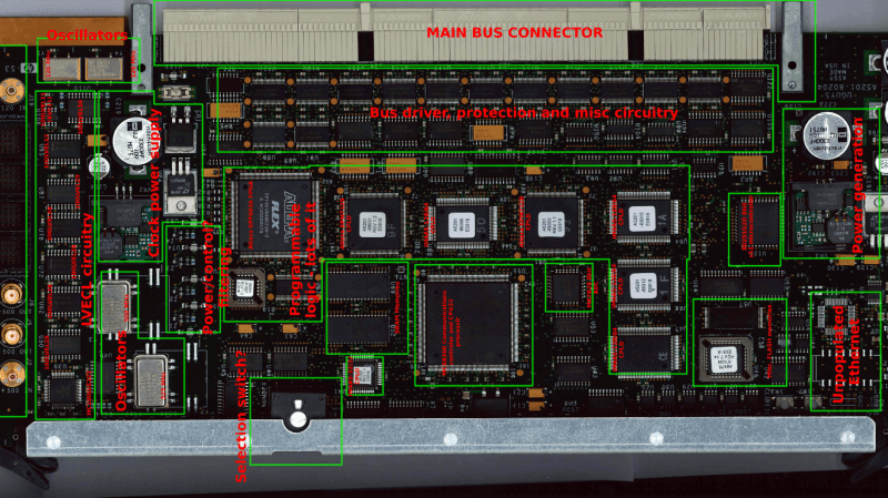
As interesting as it is to look at the insides of de-capped chips, it is equally interesting to sometimes look at old circuit boards and try to figure out the various sections, their functions, and to look at some of the design practices used. At a local electronics flea market, [daqq] recently chanced upon quite a large PCB that seemed to have come from some HP system, and picked it up for about €6 – the value of the abundant oscillators, crystals, connectors and other miscellaneous components that could be recovered seemed much more than what he paid for the board.
The board in question turned out to be from a HP 9000 Superdome system – part of the PA-8xxx based server series which packs quite a punch. This particular one was the 500MHz system UGUY5-500 board. At this point, most of [daqq]’s analysis is based on what he can visually decipher looking at the chip numbers and associated parts. He’s taken a stab at guessing the function of the board itself, and of the various parts on it. He’s put up high resolution scanned images of the board, for any of our readers who would like to offer an insight in to this board or the system that it was part of. Apparently, he has quite a few more exotic server PCB’s lined up for sleuthing, if you folks enjoy this.


Huh. Never thought I’d see Superdome stuff on HaD :)
UGUY means “Universal Glob of Utilities for Yosemite” where Yosemite was the code name for the original Superdome chipset. It is basically where all the support functionality for the cabinet is kept that isn’t big enough for its own individual cards.
The UGUY board does 3 things:
System clock source circuitry – Clock generator
Power Monitor – Temperature, power, fans, etc…
Cabinet Level Utilities – Diagnostics, cabinet hardware like LEDs, cabinet ID etc…
Yep. I support mainframes for a large hospital network, we got a couple big-boxes like the SuperDomes lying around (a couple older HP NonStops, but mostly IBM zEnterprise and s/370 boxen). And this stuff looks very similar to the ones I have kicking around.
The selector switch on the front sets whether this is a primary or backup module (Really, it sets a delay on the watchdog timer so it know when to become active if a heartbeat from another UGUY isn’t heard).
The oscillators are used to confirm that signalling is properly synchronized across the varying modules.
The HF connectors are there so that a technician can confirm whether reported timing errors are false-positives or actual faults with the modules.
As for the FPGA / CPLD, those are used to process the error signals going across the buses and to identify the actual fault coming off of them.
The ADC is used to measure temperature across the system
By the way, I would recommend hanging onto boards like this. The price my company pays for spares to keep our boxes going is insane, especially the supervisory boards and bus master modules.
Thanks for the info, I’ll update the post! I probably won’t keep it though – it’s a nice show piece, but there’s a fair amount of them on ebay. If you want it, please contact me through my page, we could work something out.
The HF connectors seem to be some sort of clock-distribution or -monitoring system.
Maybe this board was used to keep all the blades in the rack in sync. Or monitor deviation.
All the ISPs are there, so find a use of your own – unless you are planning on buying a blade server for your livingroom ;-)
If you look closely enough, you might even see the gates inside the FPGA and CPLDs. But don’t disturb them, or they will jump at you. Oh, some Flash/EPROM besides the microprocessor. Wait, it might actually store the program code of the microprocessor. Difficult isn’t it.
And some crystals for clock generation, probably divided down for the microprocessor, but where? No answer for that.
But what’s the point? Without xray machine or some good schematic, he probably won’t get that board running again. Even a schematic won’t show what’s going on inside the CPLDs and FPGAs, so quite useless/impossible to guess what the board is doing. He might sell it on ebay for somebody who restores HP-9000s for fun or use it for parts, I do the same and also have a few such boards in my PCB scrap box.
Well, the point was that it’s a pretty nice board I took high res images of just for fun, did some guessing as to what it might to, before I salvage the oscillators, the local power sources and some misc. stuff off of it. I do agree – reverse engineering it (especially considering the few ASICs there) would not be very useful… though it might be fun :)
Professor Buzzkill, we meet again.
For people who lack access to pcb x-ray services: look up photography hobbyists or photo development services in the washington area, buy 2 photographic plates and attach to either side of the PCB, add a note (and money if you want the board to be sent back) asking to develop the plate and digitize it (scanning), and your email adress. Certain snail mail routes undergo x-ray radiation, try to determine a good route by sending small thin metal plates with photographic film on both sides. Choose the route which only undergoes X-ray once (or both sides may get lit, erasing the metal shadow)… Share good routes… You heard it on HAD first…
my god that is genius!
good luck with this
even if you get it working, hp is killing off all of their old unix server lines, nobody at hp (or their customers for that matter) is interested. if you want tons of old hp server gear, just show up at any insurance company or hospital, most of them are in the process of throwing out all of their HP gear: HPUX, VMS, Tru64, it’s all going in the dumpster.
Gawd, i’d love to own one of those old HPUX monsters. They sure don’t make ‘m like that anymore!
Years ago, I was at an auction, somebody bought a half-size rack of some HP computer thing (maybe a disk subsystem). Afterwards, I saw him trying to put it in the dumpster. It was heavy, so I helped him tip it in. As it sat there upside down inside the dumpster, I said “Wow! Look at those casters!” So, I took them off and made a decent furniture dolly out of them.
Looking back, I wish I’d taken the rack, that would be cool in my workshop…
Those backplane connectors are press fit into place, so unlikely you can remove them easily. Just about the only ones you could rescue are the RF and programming connectors. The Altera CPLD is very old and their have been dropped from the current software ages ago.
SMT parts are pretty easy to recover with a hot air tool or toaster oven. Until you need a part, you are better off leaving it in place as storing them and protecting them from bent pins would takes up a lot more space.
I guess you can always practice SMT rework if you can find any use for the parts..
Thanks, I know :) I actually wanted it for the oscillators and the power supplies. And maybe the SMA connectors. The rest is nice, but not of much interest.
Do people actually *not* have old boards sitting in the parts bin anymore?
But I digress, this article makes me kind of want to pull out some of those boards and identify them.
Fans of random circuit board sleuthing should check out Bunnie’s blog, where he runs a monthly Name That Ware contest. The first person to guess the function/origin of the post’s photo gets a token prize, You gotta be quick though – somebody often nails it within hours of the post going live.