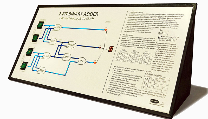
[Bob] and [Aubrey] run the System Source Computer Museum a little north of Baltimore, Maryland. For an exhibit, they thought a visual representation of digital logic and came up with a two-bit binary adder. Yes, it’s just a full adder and exactly what you would find somewhere in the second or third chapter of any digital logic textbook. The way they’re illustrating how a full adder works is the killer feature here: they’re using EL wire for all of the wires connecting the gates.
The full adder is implemented with an Arduino Mega, but the interface is the real show here. On the left side of the display there are four illuminated toggle switches that show virtual electrons flowing through EL wires, through gates and finally out to a seven-segment display. The EL wires are controlled with an EL Escudo Dos shield – a good thing, since there are a lot of lines between switches, gates, and outputs.
You can check out [Aubrey]’s demo video that also shows off how they built it below. If you’re around Baltimore, you can check out the display at the museum.


I lost all interest when I heard he chose to use an Arduino to do the digital logic.
yeah would of been a nice addition to see the digital logic all soldered up in a little peek window
How about a compromise? Use the simple logic chips for the logic, then have an arduino read the result and do the display.
Yeah, why would he want the option of adding animations (for changed wires), or swapping out the logic symbols and doing different circuits?
Totally ruins the brilliant idea of displaying the signals with EL-wire.
Also, not nearly as cool as the project you posted. Oh, wait…
Trolling is easy – doing something (anything except trolling really) is hard…
It’s a display piece, not a hacking platform. It’s not going to be rebuilt, so the Arduino instead of even a plain AVR chip is a total waste.
There are 4 switches, 11 individual el wire outputs and 7 segment led, so 22 IO, which I believe is 2 more than standard avrs. The way they chose with the mega was probably quick to program (even by a curator) and could be powered be a usb wall wart. Much better result than a pc based simulation.
The cost, for such a display is for 99% the “development time”. If for him the familiarity with arduino means that he can make it quicker with the arduino, then that’s a smart choice.
From the way he says “simple programming excercise” in the video, I suspect that the “programming excercise” took WAY more time than expected. But that’s just me.
Yeah! Oh My God! They should’ve used RPi for that!
Yeah, perish the thought someone uses the right tool for the job.
Maybe he should have used a 6502? How about a Beaglebone? An 8-core desktop gaming rig? Diode logic? Relay logic? Vacuum tubes? At what point does this become acceptable to you, phreaknik? Get over yourself already.
To be devils advocate, using the actual logic ICs for this would be trivial. Plus a BCD 7 seg driver IC.
It’s a 7480 full adder chip; that’s it.
That IC alone won’t give you access to the internal gates to show the flow, I was thinking more like 7408+7432+7486 as represented +7447
I did not at all mean to wake up the Arduino fan-boy armies, lol. I just meant that it would have been a great addition to his digital logic display if he had built it using digital logic ICs or something along those lines
Also, a consideration… It’s a lot easier to repair (by anyone with some electronics-ability), later-on, if it’s using simple, easily-locatable logic-gates…
It’s a cool demo, would be sad to see it sitting in the supply-room in a few years, because someone couldn’t (or doesn’t have the time/ability to) locate firmware to replace the processor after a lightning-storm…
I lost all interest when I saw the video was pre letter-boxed before uploading to YouTube
I did something similar for Maker Faire last year to exhibit the principal behind a 16×16 LED Matrix https://twitter.com/LEDSuit/status/467413178532392961 and https://twitter.com/LEDSuit/status/468180811494084609
Apparently I have no video of it right now, I’ll have to fix that. But behind the blue squares are the actual logic ICs, and the EL wire is truly tapped into the logic I/O lines.
(No microcontrollers involved)
Oh, and it is clocked by a 555 timer glued behind the potentiometer so people can slow it down and study the activity and speed it up to experience the effect of persistence of vision.
escudo means shield in spanish so you dont need to repeat it
Thanks, I didn’t know that. IIRC, it is also what Suzuki called their Sidekick in the Spanish market.
Awesome idea using EL wire for the demo. I’ve wanted to play around with that for some time, a visual aid would be a great idea.
Radio Shack was selling their Electrolumenesent wire CHEAP. I got 4 with a LOAD of other parts (2 Arduino Shields (Ethernet and Relay)) that fit in a bag for $5. But that party is OVER.
So, At the Top Right where:
011 = 1
+010 = 4
——————-
101 = 5
Why is it not?:
011 = 3
+010 = 2
——————
101 = 5
Nice catch, wtf?
That’s been laser engraved on.
Reblogged this on Imran's Tech Tips and commented:
2-Bit Binary Adder