Here at Hackaday we’ve covered a bunch of DIY laser diode projects. And for good reason, they are just cool. We’ve seen people add lasers to their 3D printers, stick one in a milling machine, use a highly modified scanner and even build a simple XY gantry specifically for the task. To say the least there is definitely a wide range of methods for moving around a laser but we’ve never seen anything like what [Sp4rky] sent in to us. He and his friends outfitted an old educational robot arm with a laser.
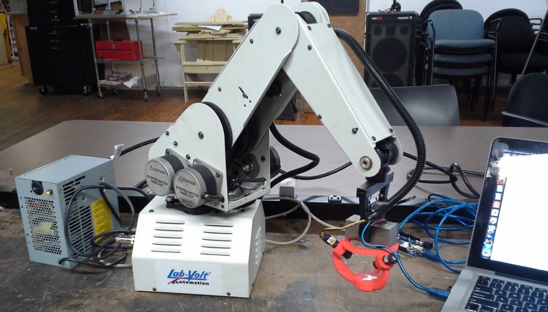
The robot arm is a 5 axis Armdroid 5100 picked up from eBay for a couple hundred dollars. It didn’t come with a controller but all of the stepper drivers were housed in the base of the arm. After a little tinkering around with the inputs the team was able to get the arm to move by sending serial commands from a PC, through an Arduino Mega which then sends the appropriate signals to the uni-polar stepper drivers. That was the easy part of the build.
The hard part was getting the arm to hold the laser at a consistent angle and height above the table. Inverse Kinematics to the rescue! Since the desired position of the laser, as well as the length of the arm segments is known, mathematical formulas can be derived to determine the necessary arm segment and joint positions while moving the laser around. The process flow starts out with an image in Inkscape, g-code is then generated with this plugin, then sent to the Arduino running a modified version of GRBL that has the inverse kinematic formulas. The Arduino directly controls the stepper drivers and the robotic arm moves. The Arduino also controls 3 constant-current laser drivers made from LM317 regulators. Three laser drivers, why?
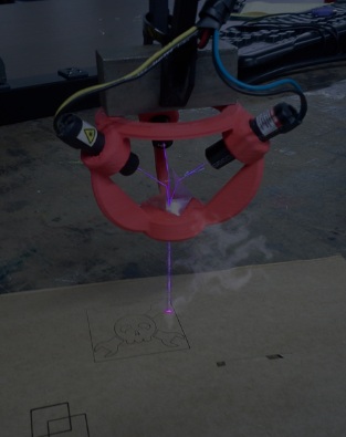 [Sp4rky] got his laser diode modules out of surplus medical equipment and, unfortunately, the rated optical wattage was quite low. Since he had 3 diodes, he decided to try to combine the 3 low power beams into one high power beam. This can be done using a prism. A prism splits sunlight into a rainbow of colors because each wavelength(color) of light that passes through the prism is bent a different amount. Since the laser diodes only put out one wavelength of light, the beam bends but does not split or diffuse. A 3D printed bracket points each laser diode at a 3-sided pyramidal prism which sends the combined beam of light straight out the bottom towards the object to be cut or engraved.
This project is cool enough that we would have covered it even if [Sp4rky] wasn’t burning a Hackaday logo. Although it doesn’t hurt for anyone wanting their project to get covered!


“Since he had 3 diodes, he decided to try to combine the 3 low power beams into one high power beam. This can be done using a prism.” HAH, good one.
Looking a little bit closer, the smoke actually looks ‘shopped…
And aligning lasers ain’t easy. Like nano-positioning-not-easy.
I think the “3 sided prism” is a giveaway. You can do it in 2 dimensions, but a three sided solid? What do they call that in geometry – impossible?
http://www.mathematische-basteleien.de/tetrahedron.htm
….That’s some fantastic counting skills you have there..
So, I assume you believe you are smart because you count the base, right? That just makes you an uneducated smartass.
A pyramid is defined by the number of sloping faces, not by the base.
i.e. A 4-sided pyramid has 5 actual faces. A TRI-angle prism has 5 actual faces.
Being a smartass doesn’t make you smart, Just your ass.
Wow, so that makes it a 3-sided solid, as was stated in the comment you replied to? That’s incredible.
If it were that easy the guys who do light shows would be doing that to combine beams for more power, instead they use elaborate knife edging to combine a bunch of laser diodes together.
Kinda wondering if this is an April Fools.
Being an ex- laser show guy, I can tell you it’s pretty tough, coming from 25 years ago of the Argon and Argon Krypton gas laser days. It was more easy to take it apart than it was to put it together for the different colors. It can be done, but you need some very sturdy mounts with some good first surface mirrors. Dust, smoke or any other ‘sticky’ particulate matter will make a mess of your mirrors in short order. Is it possible, yes, is it practical, probably not with any high reliability.
Clearly fake, but I think this is possible using a 7-sided PBS cube, connuter valve, muffler bearings, and a retro encabulator.
Yeah, but then you’d have to cantilever the airswitch with a bilateral rotary aspergillum.
don’t forget the photon displacement array
And fake protective eye-wear and breathing apparatus warning labels to protect imitation operators from the fake laser and smoke.
And thus the Death Star was conceived.
I was just going to say the same thing. Either that or the old Torchwood. (c:
This thing is the greatest!
Is that bracket available on Thingiverse?
no link to more info on the original project?
There is no original project because this is an April fools day joke.
I am not sure how this is an April Fools joke. I understand the laser beam recombination is extremely unlikely, but I dont see the puns or trollish LOLs that usually accompany an April Fools joke. At best it just seems like a misleading article that happened to be posted on April first.
Goodness. Do they at least address laser safety? This is a problem waiting to happen.
No need anymore, he’s learning Braille, also the reason that there is no link to a project…
My Laser solder paste HaD project is stuck, because I can’t afford the fireman / smelter protection suit…
Where to find the modified GRBL ?? Would be great to have further informations…! ;-))
That’s actually a mistake. This project actually uses HMSTR.
What is HMSTR ?? Is this the real April 1. joke?
is it just me, or is there no link to the project itself?
“light that passes through the prism is bent”
Even though this is just an April fools day joke you could at least use the proper terminology. Prisms refract light, they dont bend it.
Describe refraction to a 5-year-old. Hell, describe it to a 30-year-old.
Light beams bend when they pass from one material to another in which the light moves at a different speed when they don’t pass through the border between the materials at right angles. Light moves at a different speed in glass than it does in the air, so when light passes from air to glass (or vice versa), if the beam does not pass through surface of the glass at a right angle, it will bend. This bending is refraction. The wavelength of the light also affects how much the beam’s path bends, and this is how prisms split white light into the various colours of the spectrum.
I’m sure that I could make it even simpler, but I think that a 5 year old would get that (I’d have to use simpler words, but the basic explanation would stay the same)… I can test it when my little one reaches 5 ;)
“Light beams bend”
/thread
Images help the 5yr olds :P picture light as soldiers marching on pavement and then onto mud. light moves slower through glass than air, so picture the glass as mud. when the soldiers walk through the mud, they slow down and change direction based on which way they were walking on the pavement.
my embed didnt work :(
http://www.regentsprep.org/Regents/physics/phys04/crefractn/soldier.gif
Is Hackaday’s target demographic 5 years old’s?
Judging by the comments?
When things have to be simplified for the general public it can sure seem like it XD
No, it’s apparently 5 to 30.
starting to sound more like 420…
Found the arms owners blog.http://dankohn.info/finished_projects.html
No mention of this project although he did buy it on eBay with no control box. This was the subject of a blog post a while ago on HaD by the same writer.
I believe!! I must be the fool.
Jeez if you’re going to do something like this at least go the distance and use a 40W CO2 laser to make it truly terrifying!
Or you could put a magnifying glass on it and use it outdoors to harness the power of the sun.
“Inverse Kinematics to the rescue!” I’ll be making this tonight!
It did briefly cross my mind that you could add 4th / 5th axes to a standard CO2 laser cutter just by rotating the final mirror and lens. Alignment and focus would be really tricky and make it totally impractical.
Would it be possible with a fiber laser though? I’ve never seen one up close.
The ethernet port on that laptop is an open invitation to Skynet.