Putting crimp connectors on wires is one of the most tedious things you’ll do. It’s not easy, either, unless you have some practice. Before you start digging in to a pile of connectors, crimp terminals, and wire, it’s a good idea to know what you’re getting into and Gogo:tronics has a great tutorial on how to crimp electronics connectors.
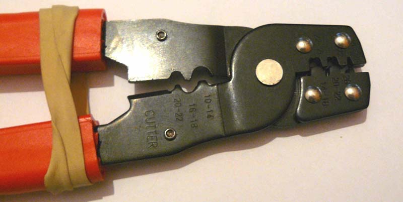
Crimping connectors onto wires requires the right tool, and the most important for this task is – surprise – the crimping pliers. These pliers press the crimping wings of the connector into each other, a task made much easier on the non-ratcheting pliers if you use a rubber band to hold the jaws of the crimping pliers open just enough to hold a crimp connector.
The general theory for crimping all types of connectors is to strip a little bit of insulation off the wire. Then, put the connector into a suitably sized space in the jaws, insert the wire, and crimp it down. For non-ratcheting pliers, it’s suggested the connector be re-crimped with the next smallest hole in the jaws.
There are a few connector-specific tips for the most common connector types, too. Dupont connectors – those flat, black connectors with a 0.1″ pitch – go together like you think they would, but for larger connectors – VH and XH-style – it’s important to use the right wire gauge and not to squish the square female part of the connector.


Personally I solder the wires in.
I leave the little contacts attached to their feed strip which I tape down to hold steady.
I melt a tiny ball of solder in between the little tabs that would normally fold over to crimp the wires.
I then get my length of trimmed and pre-tinned wire, place the tinned section on the ball of solder and heat with the iron.
I fold the little tabs that would provide strain relief to the shielding over with a small flat screwdriver and on the wires that will be connected and disconnected a lot I put a small dob of super glue on the strain relief to provide some extra support
Once completed, I clip the terminals off the feed strip and insert into the connector housing.
That does work, but I’d still suggest crimping instead of soldering unless there is a strain relief, and even still. The end of the solder is going to be the likely stress point when there is any flex on the wire. The wire strands will flex better in a crimped connection.
I mainly do it that way due to not having a crimping tool. If your after a connection that will withstand massive piles of reconnection or loads of movement then definately crimp, but lacking the tool my soldering method is pretty quick and reliable. If i know my wires will be subject to lots of movement i clamp the cable at an appropriate place so the connections are isolated from the movement.
Crimp then solder. a crimp is a lot stronger than a solder joint. but wicking in a bit of solder improved the electrical connection.
Crimp the wings down, solder, close up the insulation crimps, then liquid electrical tape to seal it up, then cover the whole thing with heat shrink tubing with a dab of silicone inside. 20 years later and the boat wiring is just fine.
Or, use hot-melt adhesive-lined heatshrink over a properly-crimped connection, apply heat, and call it done.
This is standard fare for residential well pumps, with butt splices that are subjected to vibration, reasonably high current, and continuous submersion in water. 20 years later and the pump wiring is just fine.
You can buy this as a kit at any decent hardware store.
I’ve also had excellent results from insulated terminals that come with the adhesive-lined heatshrink tubing pre-applied. The 3M version is stocked at Wal-Mart in the automotive section, and works fantastically for automotive things that see occasional exposure to the elements.
Crimped, unsoldered connections keep your car on the road. They keep your DSL and cable modem connection going. They keep airplanes in the sky. There is nothing wrong with them if the connection is (or can be) properly crimped.
(That said, sometimes the proper crimping tool isn’t available. I run into this with big terminals for big wire, or very small terminals for very small wire. At that point, I make do with whatever I can, even if that means smashing it in a bench vice with a makeshift die…and then it gets soldered. But that’s a hack.)
…And makes the connection incredibly delicate. All of the mechanical stress from any flexing of the wire will be concentrated at the point where the solder stopped wicking up the wire. If you are worried about corrosion ruining the conductivity of the crimp, then apply some dielectric grease or similar to seal out moisture etc.
No, don’t do this. A good crimp will do the job. Adding solder will cause the wire to break due to the solder wicking up under the insulation and stiffening the wire behind the terminal.
Standardize on a connector type and buy the correct crimper for it. They’re expensive, but you will never regret buying one. Sometimes you can find a crimper that will do two families of contacts, like the Molex KK and Centi-grid.
Test your crimps by pulling on the wire. A good crimp will break the wire before it pulls out of the crimp.
Is “Centi-Grid” what the “C” in “C-Grid” stands for? I always wondered about that!
The Phone Company used to consider soldered connections as temporary and crimped as permanent. A properly done gas-tight, properly stress-relieved crimped connection is actually more robust from the mechanical and electical point of view.
I had a screaming fit the other day trying to do this. It was 24 or 26AWG wire and the terminal kept jamming in the crimpers. they were the nice ratcheting ones, too. Then I found out I had ordered the complete wrong pins for the connector I was trying to assemble.
A properly done crimp is a very good connection. Properly done crimps are rare. :)
Micro JST ZH 1.5 are the bane of my existence.
Author here. I didn’t expect this to hit H-a-D. I don’t know if I’d describe it as how to “properly” crimp them, it’s just how I crimp them :-)
Here is a great document on how NASA does it:
NASA-STD 8739.4 CRIMPING, INTERCONNECTING CABLES, HARNESSES, AND WIRING
http://www.hq.nasa.gov/office/codeq/doctree/87394.pdf
Only 114 pages? Not very comprehensive, is it?
Definitely worth a read though if you want to make some seriously durable wiring harnesses for cars, boats, interplanetary spacecraft, etc.
Yes. as long as you take heed of the strict warning note on page 46: Do not use spiral wrap sleeving on mission hardware including launch vehicles.
Oddly enough, I knew that, in NASA, spiral wrap is forbidden, and that the note was in that guide without reading it.
I’d never heard that. Do you know why spiral wrap sleeving is prohibited? I’m pretty sure I’ve seen cable lacing w/ string used, so I guess that’s OK. What about plastic tie wraps?
This doc also contains good info about lap and lash splicing wires together and info about heat-shrink sheathing.
The proper source for most general purpose electronics assembly standards is the IPC guidelines. But I’d happily work to NASA standards any time. :)
I’m glad you mentioned this. I’ve learned a lot from reading the NASA stuff.
One thing I learned is crimped wires shouldn’t be soldered.
Another thing is to use transparent heat shrink tubing. I was amazed how much I like using the transparent stuff. No more wondering what the joint is like under the heat shrink.
At my last job we were required to follow the NASA standards, it was government contract work of course. Once you have to do it about a thousand times you get pretty good at it. We did did all types of crimping, from pins to RJ45 connectors.
You would think that something like this should be easy enough to figure out on your own, but I’ll admit, this is something I’ve been meaning to Google or check youtube on how it’s supposed to be done.
Now i just need the parts by the f-ton.
At least buy a set of ratcheting pliers on ebay from China. They will be about $30 or so and work really well with a decent range of most crimp sizes. Don’t waste your time with crappy tools.
As I wrote, I have both ratcheting and manual ( http://imgur.com/zL0DKZT ). I don’t like the ratcheting ones I have, they don’t work well at all for me and are very awkward to use.
With that said, there are a number of different versions of the typical ratcheting setups, I have a DN-28B the SN-28B Is perhaps more common, in theory, the die on both is supposed to do the same job, but maybe the DN die is suboptimal or different in some manner, I have not tried an SN version.
I wasn’t directing my comment at you specifically, just anybody doing crimps. It’s night and day how different the quality is.
I only paid about $1 for mine at Radio Shack. :D
Oddly, the Radio Shack crimper has served me ridiculously well for a variety of small pins. I’ve bought a few other crimpers that I thought would be better but just didn’t stand up. It seems it would do the job as well as anything short of the official one by the connector manufacturer, but that’s not going to be practical to get one for every connector type I use.
Like Mac said, a properly crimped terminal is a rare but strong thing. I did electrical assembly work for a time and we only used controlled cycle crimpers and had routine tug tests performed on connections that were overseen by an engineer.
We made things to be rugged….all circuit boards were potted, all connectors were either watertight or packed with silicone grease and things like post terminals were coated as well.
You don’t need to the extreme of routine destructive testing at home. Something as simple as giving each connection you crimp a quick tug to see if it holds goes a long way.
I just HATE it after I’ve crimped a wire and it slides out of the connector and starts laughing at me!
Step 1: purchase the proper crimping tool for the contacts that you are using
Step 2: use the tool with the proper contacts and follow the manufacturer’s instructions (this includes proper wire gauges for the contacts, etc).
Step 3: ignore all other advice from people who, especially those who claim to “know how to crimp – I don’t need to read no instructions…”
Seriously. If you are making a lot of crimps and what you are making really matters, then the “high cost” of the correct crimping tool is vanishingly small to the cost of tracking down that one bad crimp that is standing between you and a functional system, let alone the cost of having it shipped back to you for repair. Also, get a proper ratcheting tool that limits the crimping force appropriately. I can’t even count the number of failed crimps that I’ve tracked down that failed because the person who crimped the wire over-crimped and weakened/scored the stripped part of the wire so that it broke at a later date.
If you really can’t afford the proper crimping tool (and lets face it, for a lot of hobbyist work, it’s tough to justify $300 for a crimping tool when you can buy an entry level-level digital scope for that price), get one of the universal non-ratcheting crimping tools from a reputable manufacturer. I am partial to the 0638111000 by Molex Inc.
Finally, never – and I mean NEVER – solder a crimp (unless the manufacturer explicitly instructs you to do so). I’ve seen the insanity of this practice at all levels, from undergraduate project labs right up to modern R&D companies. The wire will wick the solder as far up as the wire is above the melting point of the solder, at which point the wicking will abruptly stop. That transition point between the tinned (stiff) and untinned (flexible) wire will concentrate all of the mechanical stress from bending the wire. At least you’ll know where to look for the broken conductor when the system stops working!
What’s your take on IDC crimps? They are faster with the right machinery. Do you feel they are as good?
I really like IDC crimps for things like 0.10″ pitch ribbon cable connectors, but I don’t have much experience with them elsewhere. I do like the technology, though, and it eliminates the need to strip the right amount of insulation off of a wire before crimping on the contact.
Like most things, I’d look long and hard at a specific family of connectors before committing to using them on a project. I tend to pick a few connector families and stick with them. It minimizes the tooling costs and you tend to get very good at using them rather than spreading yourself too thin over a wide range of connectors styles. That’s just my personal preference, though…
Considering there are millions of telco and ethernet jacks in walls using IDC punchdown tools, I’d say IDC is robust. Saying are they as good would require the specifics of the connection.
Soldering crimp connectors is a bad thing, and it’s something I’ve fired people over. A properly done crimp with the right tool is not improved by soldering. And anyone using superglue to hold a wire falls under crimp solderers.
Crimping connectors is faster with the right tools. Soldering is faster with the right tools. Sonic welding is faster with the right tools. Induction welding is faster with the right tools. Sex is faster with the right tools – doesn’t mean that’s the right thing to use though.
I have the 0638111000 and it is a very good and cheap tool that gets you out alot of binds. I agree with you on having the correct ratcheting tool, which although was an expensive was well worth it. If you use a ratcheting tool and there is a problem, no one can blame you for a under/over crimped crimp. It’s just less blame on you.
I have seen alot of crimps that looked pretty good at a glance, only for a little tug to pull them out.
Excellent reply and I completely agree. Never solder crimps, unless you don’t care about crimping correctly to begin with and you think are getting reliable connections by adding solder. Proper crimp tools are the solution and I will always debate a crimp connection being better than a soldered connection. I have a pull tester at work used to validate crimp connections to prove it.
RE: IDC connections: love’em. I use TE’s MTA series all the time. It’s nice when you don’t have to strip the wires. Tool wasn’t cheap, but it makes up for itself over time quite easily.
Here’s a good read on crimps, Molex’s Quality Crimp Handbook: http://www.molex.com/pdm_docs/ats/TM-638000029.pdf
I believe this is a much more detailed resource. I consider it my crimping bible
http://www.pinrepair.com/connect/
hope you’ll want to check it out
u
The only way to “Properly” crimp a connector is with the manufacturer’s own tool.
Anything else is improvising, which may or may not be reliable. JST’s crimp tools are awesome – expensive but if doing it for production will pay for themselves in the long term.
JST’s (extremely expensive) strip-feed tools are even more awesome. Their single contact tools…not so much. We have both and I overwhelmingly prefer the strip-feed tools.
A hint for using the strip feed tools: when you get a roll of contacts from Digikey, they’re rolled the wrong way to feed into the tool. If you take the roll out of Digikey’s plastic bag, reverse the direction of the roll (unroll it, then re-roll it from the other end), then put it back in the bag, you can cut a hole in the bag and feed the end of strip out of the hole, keeping the roll in the bag. Makes crimping much easier.
Slaps forehead.. That’s a really good tip! Do you know how many years I’ve used those tools in my non-dominant hand? :|
Interesting. Do they consistently roll it the wrong way?
They seem to.. Since they are on the reel correctly, if you buy less than a reel they wrap them around another spindle to count and package them. Most people buying less than a reel aren’t using strip – fed tools and you’re cutting off and crimping one at a time. I used a JST tiny-arse pitch strip fed crimper the other day and OMG they are nice! $1,500 hand tool though.. Turns out you can rent one for $25 a month.. Found it on eBay, was going to convince boss to buy it but found out they rent..
Yes and no. The original rell is rolled the “right” way, but when they pull it off the bulk reel and roll it into a bag, the put the loose end at the center, and the new cut at the outside, which is reversed from how it’s on the bulk reel…not really any other way they could do it.
Crimping is the bane of my life, how-to guide or no.
What burns my bacon is in the race to save metal many of the 9 pin D solder connectors I have bought recently have changed their spec to 26 ga. wire. Used to be 22, and with that clearance you could squeeze in 18. (Yes, I occasionally choose to run 18 gauge wire for signal…don’t ask why, but it’s saved me a a few times).
Now I’ve had to re-invent the wheel and this crimp article is nicely done. I still prefer crimp/solder/shrink tube methods though. Had more than a few crimped wires fail in a plant with tons of connections.
I only squeezed in 18 after a full days work. Heck, at 18 ga that’s practically lamp cord… Most signal wires gauges have indeed dropped over the years somebody looked at the need and the costs.
I remember drilling out two solder cups on a DB-25 connector because an engineer misread the mA rating as A on two signals, and the engineer had a custom eighteen+two wire cable ordered up with a six month delay. Took two months until I finally saw the signal specs and I cancelled the custom cable, saved 90+% of the project cost by buying off the shelf at a local company.
90% of the time the wire was never crimped properly. 10% of the time, it’s a strain relief issue. 100% of the time it’s a carbon based issue.
“I still prefer crimp/solder/shrink tube methods though. Had more than a few crimped wires fail in a plant with tons of connections.”
Hate to tell you but your crimps apparently weren’t good. Soldering the crimps would just hide that temporarily.
Here is a great guide about how to properly crimp electronics connectors
http://megadepot.com/resource/how-and-why-to-use-crimping-tools
Very informative end easy to understand
We have a crimp verification unit at work where we microsection crimps and analyze them. 20 grand gets you a basic unit. More and more companies are requiring this for production use. Major Fortune 500 companies have settled fire lawsuits due to bad crimps.
Crimping is a science, you need to have a crimp for monitor on your crimping machines. For the hobbyist, it would be wonderful if we could have a hand crimper that we could 3D print the correct crimper. Slide it on and know you are making a good crimp.
It would be really nice if you could just slide the wire into the connector. Irrigation pipe is like this, there are even some plumbing features coming out where the pipe goes into the connector, which is designed to not let it come out unless you have the proper tools. Someday, maybe they will have something like this for wires so you don’t have to go through the tedious crimping that the article describes.