showing the connector after its torn down from the side of the wire solder points, showing how thin are the metal pads, and also that one wire has already broken off

NVIDIA Power Cables Are Melting, This May Be Why

NVIDIA has recently released their lineup of 40-series graphics cards, with a novel generation of power connectors called 12VHPWR. See, the previous-generation 8-pin connectors were no longer enough to satiate the GPU’s hunger. Once cards started getting into the hands of users, surprisingly, we began seeing pictures of melted 12VHPWR plugs and sockets online — specifically, involving ATX 8-pin GPU power to 12VHPWR adapters that NVIDIA provided with their cards.

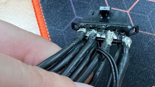
Now, [Igor Wallossek] of igor’sLAB proposes a theory about what’s going on, with convincing teardown pictures to back it up. After an unscheduled release of plastic-scented magic smoke, one of the NVIDIA-provided connectors was destructively disassembled. Turned out that these connectors weren’t crimped like we’re used to, but instead, the connectors had flat metal pads meant for wires to solder on. For power-carrying connectors, there are good reasons this isn’t the norm. That said, you can make it work, but chances are not in favor of this specific one.

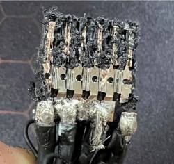
The metal pads in question seem to be far too thin and structurally unsound, as one can readily spot, their cross-section is dwarfed by the cross-section of cables soldered to them. This would create a segment of increased resistance and heat loss, exacerbated by any flexing of the thick and unwieldy cabling. Due to the metal being so thin, the stress points seem quite flimsy, as one of the metal pads straight up broke off during disassembly of the connector.

If this theory is true, the situation is a blunder to blame on NVIDIA. On the upside, the 12VHPWR standard itself seems to be viable, as there are examples of PSUs with native 12HPWR connections that don’t exhibit this problem. It seems, gamers with top-of-the-line GPUs can now empathize with the problems that we hackers have been seeing in very cheap 3D printers.

Putting Crimpers To The Test: How Good Are Our Crimp Tools?

Almost every project of mine from the last quarter century, if it has contained any wiring, has featured somewhere at least one crimp connector. There are a multiplicity of different types of crimp, but in this case I am referring to the ubiquitous variety with a red, blue, or yellow coloured plastic sleeve denoting the wire size they are designed for. They provide a physically robust and electrically sound connection that is resistant to wire fatigue due to vibration, and that can carry hefty currents at high voltages without any problems.

You might expect this to now head off into the detail of crimp connection, but my colleague Dan has already detailed what makes a good or a bad crimp. Instead recently my constant searches for weird and wonderful things to review for your entertainment led me to a new crimp tool, and thence to a curiosity about the effectiveness of different styles of tool. So I’m going to evaluate the three different crimping methods available to me, namely my shiny new ratchet crimp pliers, my aged simple crimp pliers, and for comparison an ordinary pair of pliers. I’ll take a look at the physical strength of each crimping method followed by its electrical effectiveness, but first it’s worth looking at the tools themselves.

Continue reading “Putting Crimpers To The Test: How Good Are Our Crimp Tools?”

Dirty Now Does Cables

PCB makers Dirty made a name for themselves in the prototype PCB biz, with a convenient web form and numerous options for PCB color, thickness, layers, silk screening, and so on. Now they’ve branched out into custom cabling with Dirty Cables.

You can design it yourself by dragging wires and connectors out of a sidebar and arranging them on a workspace, deciding which wire goes to what pin of the connector. Your choices for wires include various gauges and ribbon configurations. You choose a color (they have eleven) select connectors and drag those out too–choose from 17 cable-to-cable and cable-to-board connector families. We made a quick cable with four 32ga wires and two 16ga wires, with two different connectors on each side, with pricing updated realtime. If you want a sample pack of connectors, Dirty sells them for $10.

The downside to the service: there’s a minimum order of 100, though paying Shenzhen prices might make it worth your while. Just imagining crimping all of those connectors makes Hackaday’s hands hurt.

To get a sense of the diversity of connectors out there, read Elliot’s piece on the connector zoo that we published last year.

[thanks, Akiba]

How To Properly Crimp Electronics Connectors

Putting crimp connectors on wires is one of the most tedious things you’ll do. It’s not easy, either, unless you have some practice. Before you start digging in to a pile of connectors, crimp terminals, and wire, it’s a good idea to know what you’re getting into and Gogo:tronics has a great tutorial on how to crimp electronics connectors.

Crimping connectors onto wires requires the right tool, and the most important for this task is – surprise – the crimping pliers. These pliers press the crimping wings of the connector into each other, a task made much easier on the non-ratcheting pliers if you use a rubber band to hold the jaws of the crimping pliers open just enough to hold a crimp connector.

The general theory for crimping all types of connectors is to strip a little bit of insulation off the wire. Then, put the connector into a suitably sized space in the jaws, insert the wire, and crimp it down. For non-ratcheting pliers, it’s suggested the connector be re-crimped with the next smallest hole in the jaws.

There are a few connector-specific tips for the most common connector types, too. Dupont connectors – those flat, black connectors with a 0.1″ pitch – go together like you think they would, but for larger connectors – VH and XH-style – it’s important to use the right wire gauge and not to squish the square female part of the connector.