Disappointing news this week for those longing for same-hour Amazon delivery as the retail giant tapped the brakes on its Prime Air drone deliveries. The pause is partially blamed on a December incident at the company’s Pendleton, Oregon test facility, where two MK30 delivery drones collided in midair during light rain conditions. A Bloomberg report states that the crash, which resulted in one of the drones catching fire on the ground, was due to a software error related to the weather. As a result, they decided to ground their entire fleet, which provides 60-minute delivery to test markets in Arizona and Texas, until a software update can be issued.
The announcement of Autodesk’s changes to the Fusion 360 personal use license terms this week caused quite a dustup. Our article on the announcement garnered a lot of discussion and not a few heated comments. At the end of the day, though, Autodesk is going to do what it’s going to do, and the Fusion 360 user community is just going to have to figure out how to deal with the changes. One person who decided to do something other than complain is Justin Nesselrotte, who came up with a quick and easy bulk export tool for Fusion 360. This gets to the heart of the issue since the removal of export to STEP, IGES, and SAT files is perhaps the most painful change for our community. Justin’s script automatically opens every design and exports it to the file type of your choice. Since the license changes go into effect on October 1, you’d better get cracking if you want to export your designs.
Over on Twitter, Hackaday superfriend Timon gives us a valuable lesson in “you get what you pay for.” He found that a bunch of his header pin jumper cables weren’t even remotely assembled properly. The conductors of the jumper wire were only loosely inserted into the terminal’s crimp, where apparently no crimping pressure had been applied. The wires were just rattling around inside the crimp, rather than making sold contact. We’ve covered the art and science of crimping before, and it’s pretty safe to say that these jumpers are garbage. So if you’re seeing weird results with a circuit, you might want to take a good, close look at your jumpers. And as always, caveat emptor.
The GNU Radio Conference wrapped up this week, in virtual format as so many other conferences have been this year, and it generated a load of interesting talks. They’ve got each day’s proceedings over on their YouTube channel, so the videos are pretty long; luckily, each day’s stream is indexed on the playbar, so along with the full schedule you can quickly find the talks you’re interested in. One that caught our eye was a talk on the Radio Resilience Competition, a hardware challenge where participants compete head-to-head using SDRs to get signals through in an adversarial environment. It sounds like a fascinating challenge for the RF inclined. More details about registering for the competition can be had on the Radio Resilience website.
You know those recipe sites that give you a few choices on what to make for dinner based on the ingredients you have on hand? We always thought that was a clever idea, and now something like it has come to our world. It’s called DIY Hub, and it aims to guide makers toward projects they can build based on the parts they have on hand. Users create projects on the site, either hosting the project directly on the site or providing a link to projects on another site. Either way, the project’s BOM is cataloged so that users can find something to build based on parts stored in their “Garage”. Granted, most of us suffer from the exact opposite problem of not knowing what to build next, but this could be an interesting tool for stimulating the creative process, especially for teachers and parents. It’s currently in beta, and we’d love to see a few Hackaday.io projects added to the site.
And finally, we got a tip to an oldie but a goodie: How to Build a Castle. No, we don’t expect to see a rash of 13th-century castle builds gracing our pages anytime soon — although we certainly wouldn’t be opposed to the idea. Rather, this is a little something for your binge-watching pleasure. The BBC series, which was actually called Secrets of the Castle, was a five-part 2014 offering that went into great detail on the construction of Guédelon Castle, an experimental archaeology project in France that seeks to build a castle using only the materials and methods available in the 1200s. The series is hosted by historian Ruth Goodman and archaeologists Peter Ginn and Tom Pinfold, and it’s great fun for anyone interested in history and technology.
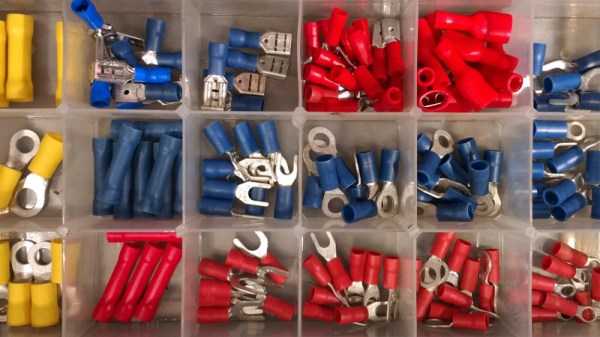
Almost every project of mine from the last quarter century, if it has contained any wiring, has featured somewhere at least one crimp connector. There are a multiplicity of different types of crimp, but in this case I am referring to the ubiquitous variety with a red, blue, or yellow coloured plastic sleeve denoting the wire size they are designed for. They provide a physically robust and electrically sound connection that is resistant to wire fatigue due to vibration, and that can carry hefty currents at high voltages without any problems.
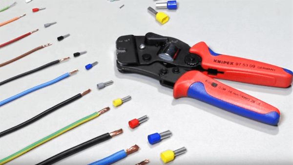
You might expect this to now head off into the detail of crimp connection, but my colleague Dan has already detailed what makes a good or a bad crimp. Instead recently my constant searches for weird and wonderful things to review for your entertainment led me to a new crimp tool, and thence to a curiosity about the effectiveness of different styles of tool. So I’m going to evaluate the three different crimping methods available to me, namely my shiny new ratchet crimp pliers, my aged simple crimp pliers, and for comparison an ordinary pair of pliers. I’ll take a look at the physical strength of each crimping method followed by its electrical effectiveness, but first it’s worth looking at the tools themselves.
We recently posted about a spectacular 3D-printer fire that was thankfully caught and extinguished before spreading to the hacker’s house or injuring his family. Analyzing the remains of the printer, the hacker determined that the fire was caused when a loose grub screw let the extruder’s heater cartridge fall out and touch the ABS fan shroud. It ran full-on and set things on fire.
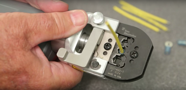
A number of us have similar 3D printers, so the comments for this article were understandably lively, but one comment stood out by listing a number of best practices for wiring, including the use of ferrules. In particular, many 3D printers connect the heated bed, which draws a lot of current, with screw terminals to the motherboard. While not the cause of the fire in the original post, melted terminal blocks are a common complaint with many DIY 3D printer kits, and one reason is that simply jamming thick stranded wire into a screw terminal and hoping for the best can result in increased resistance, and heat, at the joint. In such situations, the absolutely right thing to do is to crimp on a ferrule. So let’s talk about that.
In my misspent youth I found myself doing clinical rotations at a local hospital. My fellow students and I were the lowest of the low on the hospital pecking order, being the ones doing the bulk of the work in the department and paying for the privilege to do so. As such, our locker facilities were somewhat subpar: a corner of a closet behind a door labeled “COMMS”.
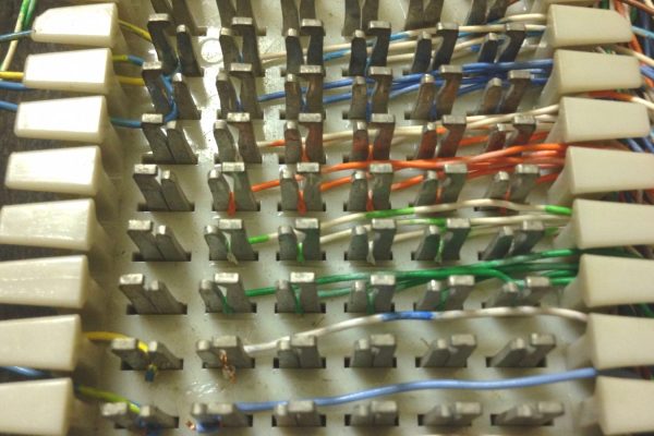
In the room was a broken chair and a couple of hooks on the wall for our coats, along with an intriguing (to me) electrical panel. It had a series of rectangular blocks with pins projecting from it. Each block had a thick cable with many pairs of thin, colorful wires fanned out and neatly connected to the left side, and a rats nest of blue and white wires along the right side. We were told not to touch the board. I touched it nonetheless.
I would later learn that these were Type 66 punchdown blocks for the department’s phone system, and I’d end up using quite a few of them over my hacking life. Punchdown connectors were a staple of both private and public telco physical plants for decades, and belong to a class of electrical connections called insulation displacement connections, or IDC. We’ve recently looked at how crimp connections work, and what exactly is going on inside a solder joint. I thought it might be nice to round things out with a little bit about the workings of IDC.
I had a friend who was an electronics assembly tech for a big defense contractor. He was a production floor guy who had a chip on his shoulder for the engineers with their fancy book-learnin’ who couldn’t figure out the simplest problems. He claimed that one assembly wasn’t passing QC and a bunch of the guys in ties couldn’t figure it out. He sidled up to assess the situation and delivered his two-word diagnosis: “Bad crimp.” The dodgy connector was re-worked and the assembly passed, much to the chagrin of the guys in the short-sleeved shirts.
Aside from the object lesson in experience sometimes trumping education, I always wondered about that “bad crimp” proclamation. What could go wrong with a crimp to so subtly futz with a circuit that engineers were baffled? How is it that we can rely on such a simple technology to wire up so much of the modern world? What exactly is going on inside a crimped connection anyway?
Putting crimp connectors on wires is one of the most tedious things you’ll do. It’s not easy, either, unless you have some practice. Before you start digging in to a pile of connectors, crimp terminals, and wire, it’s a good idea to know what you’re getting into and Gogo:tronics has a great tutorial on how to crimp electronics connectors.
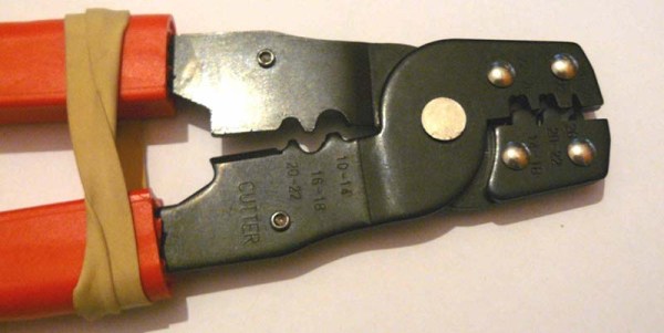
Crimping connectors onto wires requires the right tool, and the most important for this task is – surprise – the crimping pliers. These pliers press the crimping wings of the connector into each other, a task made much easier on the non-ratcheting pliers if you use a rubber band to hold the jaws of the crimping pliers open just enough to hold a crimp connector.
The general theory for crimping all types of connectors is to strip a little bit of insulation off the wire. Then, put the connector into a suitably sized space in the jaws, insert the wire, and crimp it down. For non-ratcheting pliers, it’s suggested the connector be re-crimped with the next smallest hole in the jaws.
There are a few connector-specific tips for the most common connector types, too. Dupont connectors – those flat, black connectors with a 0.1″ pitch – go together like you think they would, but for larger connectors – VH and XH-style – it’s important to use the right wire gauge and not to squish the square female part of the connector.