Amazon has been getting creepier and creepier lately with their recommendations. Every time I log in, I’m presented with a list of new Blinky LEDs, Raspberry Pi accessories, Arduino shields, and the like. It’s as if they know me. Their customer database paid off when it recommended a $22 transistor / component tester. I’ve been seeing those testers around quite a bit lately. Curiosity got the better of me and my mouse found its way to the “Buy it now with one click” button. Two days later I had a “SainSmart Mega328 Transistor Tester Diode Triode Capacitance ESR Meter MOS/PNP/NPN L/C/R” in my hands.
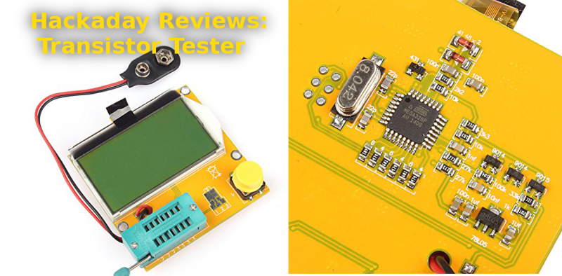
I’m going to get the obvious out of the way. This thing is built cheap – as cheap as the factories can make it. My particular unit arrived with the LCD flapping in the breeze, hanging on by its flex cable. Fitting the LCD back into the acrylic backlight frame revealed a slightly worrisome twist in that same flex. Thankfully nothing was actually damaged, though I do want to give the flex cable some protection in the future. More on that later. The circuitry was open for all the world to see on the bottom of the tester. The heart of the unit is an ATmega328. Supporting it are a few transistors and a handful of passives.
I didn’t have huge expectations for the tester, but I hoped it would at least power up. Hooking up a 9 volt battery and pressing the magic button brought the tester to life. Since I didn’t have anything in the socket, it quickly lit up and displayed its maker information – “91make.taobao.com”, and “By Efan & HaoQixin”, then it informed me that I had “No, unknown, or damaged part”.
I had a few resistors lying around the bench (doesn’t everyone?) so I put one in. The tester read it as 9881 ohms. Sure enough, it was a 10K 5% resistor. Capacitors – ceramic disc, electrolytic, and surface mount all worked as well. The tester even provided ESR values. The real test would be a transistor. I pulled an old 2N2222 in a TO-18 metal can, and popped it in the tester. The damn thing worked – it showed the schematic symbol for an NPN transistor with Collector, Base, and Emitter connected to Pins 1,2,and 3 respectively. Flipping the pins around and re-testing worked as well. The tester showed hFe as 216, and forward voltage as 692 mV, both reasonable numbers for a 2N2222.
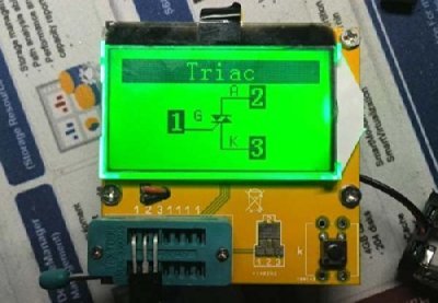 The tester worked surprisingly well – it was able to correctly identify BJTs, FETs, even esoteric parts. The only thing it balked on was a linear voltage regulator, which showed up as two diodes. Regulators are a bit more than a simple device though, so I can’t blame the tester there. The values returned were all reasonable as well. While I don’t have a calibrated lab to check against, the numbers lined up with my Fluke meter.
So what exactly is driving this little tester? There are about 20 versions of it on the market, all of them from China. 91make is a seller on taobao.com, often referred to as “China’s ebay.” 91make’s front page features no less than 7 versions of the transistor tester, with various cases and LCDs. Some digging turned up the history on this device. It turns out the transistor tester is an open source hardware project (translated) originally created by [Markus Frejek], and built upon by [Karl-Heinz Kubbeler] and a number of others. The Subversion repository for the project shows it is quite active, with the most recent check-in only a few hours ago. The project is also well documented. The English PDF is 103 pages, explaining theory of operation, the circuit itself, and the software. The document even explains some of the shortcomings of the Chinese versions of the tester, including using a zener diode where the original schematic calls for a precision 2.5V reference. Yes, it will work, but it won’t be as accurate as the original.
The devs also don’t officially support the clones which I can understand, considering the quality and changes in design each manufacturer is baking in to their own version. There is a huge thread on the EEVblog forum covering these testers. Some can be modified to be closer to the official version. In fact, with an ISP tool the intrepid hacker can update the firmware to the current rev from [Karl-Heinz’s] repository.
So the final verdict on this tester is that it is a thumbs up with a small caveat. These testers are built down to a cost (and that cost is as close to zero as possible). They’re great for sorting parts, but they’re no substitute for a higher quality measuring device. I’d also love to see a version that supports the original developers.


I have this design of the tester too, and I must say it was definitely worth the $15 or so it cost on ebay. It would have been nice to have a more standard one, though, as I’m not even sure how to get into the settings menu on this customized ‘efan’ version.
Is this particular tester able to be updated to the latest “mainstream” firmware? I know there are differences in display devices across the multiple different tester clones, some of which aren’t fully supported in the main firmware. The ‘128×64’-style display on this tester, with an unusual driver chip, wasn’t supported by the main firmware last time I looked, maybe it is now?
The other thing I think is worth mentioning about this particular model is the annoying placement of the feet, wherein the button and the test socket are hanging cantilevered away from the supported area of the board, and the whole tester seesaws back and forth as you operate the zif socket / press the button. It’s really quite an annoying design oversight, actually.
You got feet? My board had no such luxuries. Probably eliminated as a cost cutting measure.
I glued on some cheap, harbor freight rubber grommets and the problem went away.
Can I get the link for the exact model you have.
This is the exact link for mine: http://www.amazon.com/SainSmart-Mega328-Transistor-Tester-Capacitance/dp/B00OWS9YW6 However, it was in stock for prime shipment when I bought it a few weeks ago.
Order placed! I have trays of components dating back to the 1970’s with long forgotten part ID and pinouts. This thing will pay for itself in about an hour.
My first one of these failed, so I had to buy a new one.
The flat ribbon connector to the display will eventually break due to flex-stress, so don’t get one without the case.
Let me repeat: Don’t get one without the case. The flex cable will break in a couple of weeks. Spend the extra money for the cased version that protects the display cable.
I cut a case from Acrylic using our laser cutter. If anyone’s interested, I can post a link to the files as a reply to this comment. (Need to go to the space to get/convert them – will take a couple of hours.)
The unit is remarkably useful. It detects the *type* of device, and shows useful information such as the effective capacitance of diodes, the beta of transistors, and so on. It even sorts out which leads are which (E, B, C).
I made a set of alligator clips that connect with zif socket.
It’s a good buy, I recommend it.
My case:
Try this again. My case:
https://www.dropbox.com/s/r24kvu9yh97rr2d/DSCF1140.jpg?dl=0
I’d really like the files for your case if at all possible. I just ordered one, will save me designing my own. Thanks!
This is a pretty cool little tool. It is a pity about the chinese-quality construction though. I did look through the project page (at least briefly), and I couldn’t find any reference for buying hardware. I did find a DIY build (ebay) for $15.49 US.
All the models I have looked at have either a 2*16 character display, or an graphics LCD display; and either a 14 pin ZIF socket, or some form of three pin connection.
I have this version-
http://www.aliexpress.com/item/Small-12864-LCD-Transistor-Tester-Capacitance-ESR-Meter-Diode-Triode-MOS-LCR-NPN/32221279847.html
I really like it. The accuracy is adequate for my use, and I find myself using the surface mount pads on it to test components.
That looks like a Fish8840 version. There is a mod you can do to prevent it from discharging the battery unnecessarily when it is “switched off.”
Cool. I will look for that. Thanks!
Here’s a site where someone did some testing on that version.-
http://lygte-info.dk/review/ComponentTester%20Fish8840%20UK.html
I think I got the same one, just the other day. I’ll admit that all other things looking fairly equivalent between the different ones the Autobots, the red lacquer, and “DROK” sold me on that particular one. Aside from not having a battery clip somewhere on the assembly it seems to be pretty solid, and works a treat for figuring out what those little tiny things are without having to bust out the magnifier.
Aliexpress will Rip-You Off !!!!
I have one of the models with the 2×16 character display. I mounted it in a cheap plastic food container and use it whenever I am working on solid state gear (as opposed to vacuum tube). It is mainly a quick way to check transistors or the odd part that I can’t quite read the markings on. Had it for over a year and it is still working fine even though the battery is down to 8.2v
Are you using for in circuit (unpowered) readings?
Adam,
you didn’t mention if yours has the zener or the 2.5 volt regulator.
I’m guessing it is using a zener, because it was made in China.
Can the firmware on yours be (easily) updated?
How (far?) from the current version of firmware is yours?
Thank you!
It was nice to see that a “transistor checker” also measured passive components as well.
Oh, did you try an inductor?
My version is zener. There is an ISP header, so it can be programmed. The LCD backlight would have to be removed to solder the header down though. I haven’t tried a coil yet – I’m going to need to find one in my parts bin and give it a go!
You don’t have to remove the backlight — those 6 pins on the back next to the crystal are the ISP header too. All you have to do is make a mirror-image ISP connector to use them.
But then you’ll really need to add feet.
My understanding is that an external reference doesn’t make that big a difference on versions with the crystal and suitable precision on key resistors, because the internal calibration routines compensate appropriately.
Speaking of which, to run the self-test, short all three channels together before starting the device. This will trigger the self-test on all the variants I’ve tried it on. Follow the instructions. It will do some tests with the channels shorted, then ask you to remove the short, perform some more tests, and finally, ask for a >100nF cap between channels 1 & 3. I haven’t checked carefully, but I’m pretty sure all the versions I’ve tried take advantage of the option in he mainline firmware to store the test results for calibration of the instrument.
A zener is temperature dependent, so the calibration won’t help.
That’s an amazing list of capabilities for such a simple and inexpensive device. Will have to get one. Thanks for the review, and especially for searching out the real creator of it!
I have one question. Looking at the schematic, I can figure out how it implements every measurement/test, except *inductance*. The only way I know to measure that is by adding a capacitor, and seeing what frequency the resulting LC circuit oscillates at. But there’s no capacitor. Unless they’re somehow (mis)using the internal sample-and-hold capacitor on the ATmega’s ADC pins as the C part of the LC, and since that’s tiny it might explain why it can’t measure below 10uH; but that’s just a wild guess. Anyone know for certain how this device measures inductance?
If there’s a resistor in series with the device, when you put a step-change of voltage you can measure the current through the resistor over time (via its voltage). Capacitor jumps high and decays low, inductor starts low and exponentially builds.
Measure the exponential slope and invert the timing formula to get inductance.
The slope of the exponential is — ta da! The exponential.
PWalsh has the answer below – but you should definitely check out the english “Doku” pdf in found on the original svn repository I linked. Section 5.4 explains the inductance measurement, and even includes a graph of numerous measurements (and associated errors) using various ATmega parts.
Thanks [PWalsh] and [Adam Fabio]. I didn’t consider current rise through a resistor a usable method, because the time constants are typically so small. But after a little searching through the SVN I found the description. There’s a comparator on one of the ATmega pins used for measurement, and along with a timer, it’s able to measure with the required resolution. Makes sense now, thanks again to both of you!
Seem to take a long time to review this. These testers have been around for ages.
I agree. Good little tool for how cheap it is. But made like shit. But then it does come from China. The land of cheap.
Bullshit. My most expensive gear was made in china, and I have moderately priced gear that was both designed and made in china.
If China is land of the cheap, its not because that’s all they can or do do, its that no one else can do anything cheaper, at least not right now.
And when it comes down to it, yeah, these things are cheap. You can get them shipped to you for less than $15 on ebay. And for less than $20, you can get one that is quite close to the original schematic, with thru hole parts and a socketed MCU for easy hacking. Look for the GM328 from EZM Electronics studio. Quality is just fine, for a device without a case.
There’s a reason your expensive gear was “made in China”. China can do good stuff (KZ is one of my favorite IEMs), but it’s usually rare to see someone do it.
Right on dude, it isn’t where it is made that makes the difference! These things are low cost because someone figured out how to do the job by using inexpensive parts, such as atmega chips. The old test devices relied on lots of individual components which added to cost of production simply due to big circuits and big boxes. When a job can be done with software instead of hardware, expect the price to go down.
Adam, in your looking around at the official source, is there a place to get pre-built or kits of the official one? Digging through SVN and the translated webpage doesn’t point to an official distributor. I’d prefer to get one from them (or the EEVblog supply chains) but if one doesn’t exist then that chinese-ebay seems good enough to add to my tool bench.
I’ve got a bunch of PNPs I had meant to match for some guitar effects, but they have just been sitting for years. $30 or even $50 to encourage me to build a few pedals is a small price.
I did look for an official version to link to in the article – but no such luck. The best place to ask would probably be the EEVblog forum – [madires], who is a regular on there says he’s one of the developers.
Wouldn’t you need a curve tracer for matching transistors? From the description, this tool won’t get you there. You are far better buying matching transistor pairs on a chip these days.
I don’t think anything exists, other than the occasional group by. Look for the “GM328” version on ebay. It should have greenish PCBs, a socketed MCU, and (mostly) thru-hole components. My understanding is that it is pretty close to the original design.
I haven’t figured out how to order directly from TaoBao yet, but the chinese ebay sellers who sell these have reasonably good prices and quick delivery.
Erg… “group buy,” not “group by”
its also one of the cheapest ways to get your hands on an ESR tester – girls best friend when fixing electronics.
I was all gearing myself up to build a test board with some AC and leds to identify bases on transistors (NPN OR PNP?), when i decided I could do it with an avr, which rapidly led me to just forking out the $8 (I have a text screen, not graphic) to get one of these. Awesome tool, I can read inductors and small capacitors that the settings on my meter just cant get to. It nonally tells me what pins are what of the transistors there is no data in the world on, but pointed out i have a whole pile of JFETS and to-92 SCRs (talk about getting giddy!)
This costs less than making one yourself, open source software, verry usefull. It made a fun job of clearing up the hard to identify parts in theh junk bin. I went thru my TO-3’s and found out 40% of them were just scrap metal.
BE AWARE if it goes into ‘calibration mode’ its because you have a “direct short” between all 3 pins (its that same burned out TO-3 every time)
SUGGESTION make a wall power adapter for it!
(is this ’22’ ceramic 22pf of 200pf?)
On the topic of open source, I have been looking for a copy of the AVR code to load into an Atmel 328, I have a hand full of those on hand. Have not been able to track down a good working copy of the code to burn. 8 $’s is sure cheap enough to just get one of these. Was just wondering, if I got one, plugging the chip into an Arduino and see if the file will transfer to my program im my laptop. I’ve been looking at the schematic and thinking about just building on one a proto board to see if I can make it work.
As I bought a BK Precision in circuit transistor test at an estate auction years ago I’m not in the market for a transistor tester. But it would great to see either kits or homebrew projects for other test gear.
Yeah, I own one of BK’s Transistor Checkers, bought it for $10 at auction.
2 testers that I have that are not from china:
https://c4.staticflickr.com/8/7211/7303669578_fd3e444b37_z.jpg
and
https://c2.staticflickr.com/8/7105/7376693682_6d5b0a8978_z.jpg
the simpson is pretty simple but the leader has a crapload of chips inside, from the 80’s or maybe even a bit earlier. it does auto ID bipolars and fets and does some other simple tests. but they both have charm; which is missing from the ‘dead in a week’ ebay wonders…
The Simpson 260 remember me of my college years in the 70’s. The transistor tester is an optional module.
http://www.simpson260.com/downloads/simpson_260-afp-1_user_manual-1969.pdf
Wow! this analog multimeter is still in sale.
http://www.simpsonelectric.com/products/test-equipment/vom-multimeters/260-6xlm-260-6lpm-low-ohms
Yes, and it only costs $330 (US) on ebay. That’s 16 times as much as the testers under discussion. I am sure that the Simpson will probably be able to be passed down to your grandchildren (my dad has a Simpson multimeter that he uses occasionally for automotive checks, and it works fine), but it’s apples & oranges.
I’m not trying to be a troll, just curious what the price was, and figured I’d post it.
I had a great admiration for this tester. A long time ago when I was part of a local microcontroller club I would recommend this device to people to built. It was the old version with 2x16LCD and it sure cost a lot more to make than current ebay prices, but it’s the best addition to a multimeter that you can get.
Definitely intrigued… I tried to design something like this a while back, called it the TPIDer (three-pin identifier)… Put in quite a bit of work, but didn’t get very far. I’m glad to see it’s possible!
So, wait, do I understand correctly that this thing actually identifies the pinout, as well? As in you can plug in any ol’ three-pin transistor/FET/whatever in any orientation, and it’ll give you the polarity, pinout (and more)?
exxxcelllennnntttt.
A very simple bijunction transistor checker requiring a PIC10F202 or an AtTiny13a (both source code available on https://github.com/Picatout/transistor-tester)
details (french) at http://picatout-jd.blogspot.ca/2013/03/verificateur-de-transistor.html
The checker only tell if the transistor is OK an if it is PNP or NPN.
blinking GREEN LED good NPN transistor
blinking RED LED good PNP gransistor
Hmmm…extreme utility and ease of use yet poor build quality and update-abilty. This looks like a job for Adafruit or similar to improve. I think people would spend some extra coin for something this darn useful yet not yet well-made nor available as a kit.
Also HF has their multi-function multimeters that will test inductors, semiconductors and the like (and which are insanely cheap on sale), but I haven’t run through them for precision in those capacities.
Turns out EBay has a ton of these in cases for just under $30 – no firmware updatability though…
I should probably get off my ass and finish a video I started comparing three different versions of this device.
In the meantime though, I’ve learned that most of the versions on ebay originate from ~3 different small electronics outfits in China. Adam identified one of them, “91Make,” but there is also Fish8840 and EZM Electronics studio. All of them offer both bare bones versions like this one, and “finished” models in cases.
None of them release firmware updates, and none of them release source for their version of the firmware. Fish8840 and 91Make seem to have modified the mainline firmware pretty extensively for graphical display. EZM though seems to keep pretty close to the mainline. Fortunately, people have been successful at getting recent versions from all three manufacturers to work with the mainline firmware by changing a few config options in the makefile and recompiling. The details are in that thread in EEVBlog, starting around page 54 or so.
My take is that the 91Make version has done the best job on output on a graphical display. The Fish8840 version has a number of problems. I think the graphics for various transistors are too heavy and hard to read, and there is some stupidity in the design of the power supply section that causes it to waste battery when “off.” (There is video on how to fix it, and the fix may even be documented in the docs for the mainline firmware).
The EZM Electronics Studio version is probably my favorite because out of the box, it supports the fullest range of options from the mainline firmware and because it uses a socketed MCU and (mostly) through-hole components with appropriate tolerances. The downside is that, since it is using the mainline firmware, its use of the graphical display isn’t as refined, also, the SMD device test pads are perhaps the least flexible of the three designs.
The EZM Electronics version is usually listed on ebay using “GM328” in the title, the socketed MCU and through-hole components are obvious in the product photos of the version with the graphical display, but are obsured by the display on versions with the two line text display. They’ve recently released a SMD version that may be listed as GM328A. Their “finished” version in a case is often labeled “MK-328” and comes with three leads/test clips and a module with a ZIF socket and SMD test pads.
I’d be very surprised if there is no way to update the firmware on the finished versions from EZM or any of the other manufacturers.
The Firmware / Hardware / Docs for the Fish8840 version can be found here-
http://www.mikrocontroller.net/svnbrowser/transistortester/
What a coincidence! I’ve ordered this version and will be assembling it today:
http://www.banggood.com/DIY-Meter-Tester-Kit-For-Capacitance-ESR-Inductance-Resistor-NPN-PNP-p-929603.html
This one uses high quality parts: TL431AA precision voltage reference, professional PCB with good layout, plating and silkscreen and all parts are through-hole for easy assembly. I’ll also wire up an ISP connector for upgrading the firmware.
The documentation in the SVN repo is outstanding, featuring very thorough accuracy comparisons with professional measuring instruments. Cheap, useful, well made and hackable — ticks all the boxes!
Does someone have a link to purchase a pre-assembled with the 2.5V precision reference?
When I put in Darlington transistor on V2.07 software it gives about correct forward voltage as 1.13 Volts but only says “PNP” I think it should say “PNP Darlington” or maybe abbreviated equivalent. Hfe of 44 seems a bit low for BD648 (unused), But I realized maybe the test current is not enough for power transistors.
Now I would like to come back to this webpage and read more but it this web page used up 3.246 Megabytes of mobile data and mobile data is very expensive in New Zealand, Data used to last a long time on slow dial up 54k speed, but not now with super fast internet. because of data hungry websites (I call obese websites)
unused (TO22 case) SCR BT151, shows up as NPN Cathode (Emitter) Anode (Gate) Gate (Base)
hFE = 0 , Uf = 0mV
I’ve made a design for a case for this device, suitable for 3D printing. There are several places you can order a 3D print if you do not have a printer yourself. https://www.thingiverse.com/thing:1920077
How hard would it be to replace the zener with a 2.5v reference?
Using the lt1004 as originally designed? Probably not hard at all (unless the zener is buried under other stuff.) Simply unsolder the zener and then solder in the lt1004 in it’s place (get one of the through-hole models and then just solder the legs to the pads.) See http://www.analog.com/media/en/technical-documentation/data-sheets/1004fc.pdf?domain=www.linear.com where it shows it only uses 2 pins, even though the to-92 version has three and the 8-pin version has….)
If you got something cheaper (and maybe not quite as precise) like an LM431 (http://www.ti.com/lit/ds/symlink/lm431.pdf) you would need to make a small daughter board since it needs a couple of passives.
Actually, one of the manufacturers uses an LM431 (cathode, anode and refV pins) without any passives simply by tying the cathode and refV pins together. See https://github.com/tardate/LittleArduinoProjects/tree/master/Equipment/ComponentTesterKit
Sorry for bringing this thread back from the dead but I just learned about these cool little testers. I am an electronics hobbyist (not an EE) but these would be super helpful to identify components in my parts bins. Despite reading the comments here and on the EEVBlog, it’s hard to keep track of what’s what. Is there a particular model or keyword I can use to find the latest/(agreed on) best version to buy on Aliexpress, Banggood, eBay, etc? Thank you.
I am also interested in the current set of recommendations! Thnaks for bringing the thread alive again!
i want the coding code for transister. are u have it?
I have one of these for a while. They worked just fine, which is to say superb with such a low price.
My PC power supply was bad. I removed 4 1000uf electrolytic capacitors and checked them with this gadget. Somehow all 4 of them show up as diodes. I went back to eBay and found an identical looking unit. The description says the capacitance range is 25pf -100,000 uf, so 1000uf is covered.
Is my meter wrong or all 4 caps went bad at the same time?
careful with testing caps. You MUST discharge the caps by shorting their leads before attaching, as the surge from stored energy can fry these. There is also discussion on the EEVblog thread on building a protection circuit, but I do not recall on what page of the thread.
You might wanna try a few other known good components to verify whether your tester survived.
I’m not that satisfied with it’s performance when inductors under 1000uH are tested. There is another project for precise LC meter and unfortunately, the transistor tester did NOT borrow the good stuff from it.
Could you put a link to that project?
For anyone wondering which version to get here’s a limited experience with what i got. I was and still am a bit confused with all the versions out there.
I JUST got myself the version, which is apparently called AY-AT kit (you won’t find it with that keyword from the shop sites though and it’s not called that in the official manual).
There’s two (to my knowledge) versions of the kit (mentioned in the official manual and seen in the shop sites), the one with 128×64 (controller ST7565) display and the newer one with a 160×128 color display (controller ST7735). I got the one with 160×128 color display. Here’s a link to an awesome review about it:
https://github.com/tardate/LittleArduinoProjects/tree/master/Equipment/ComponentTesterKit
which includes a link to this:
http://www.instructables.com/id/My-Guide-to-AVR-Transistortesters/?ALLSTEPS
Current official manual (a link to the repository mentioned in the review):
https://github.com/svn2github/transistortester/tree/master/Doku/tags/english/ttester_eng112k.pdf
Discussion forum as mentioned in the review):
http://www.eevblog.com/forum/testgear/$20-lcr-esr-transistor-checker-project/
Why a kit:
This one uses 99% of through hole components and the couple SMDs have already been soldered to the PCB. It is easier to modify than the versions with SMD components, if need be.
Warnings:
BE CAREFUL with the display. The display is attached to the display module PCB by only the 2 flat cables. If you turn the display over, it will hang from the flat cables and they can easily get cut. Tape the display to the display PCB immediately, after which you can do something more permanent like hot glue or an actual case or whatever. I knew this and i still flipped the display before tapeing it, but fortunately the cables were ok.
Someone had a scratch on the PCB, which had cut one of the tracks and the device did not work, so before soldering, check the PCB for scrathes and test the tracks if you have any doubts.
The good:
Easy to assemble, easy to modify, nice display, has a voltage reference (TL431) instead of the zener diode, but apparently it is a not a very good voltage reference, so it might need to be replaced.
The bad:
The precision resistors R1 to R6 (in the official manual, R9 to R14 in the linked review) (of 680 and 470K, 3x each type) are not very precise. I’m going to replace them with real precision resistors.
The version came with quite old software, 1.12k. The official software is at 1.27 and i’m going to update ASAP even though it means i will lose the temperature sensor and IR tests, but i will gain new part tests and servo tests atleast.
The MCU programming pins have not been layed down to the PCB, so i will have to figure that out, etiher lay down some kind of wires and connector or just remove the MCU from the socket and program it separately.
As mentioned, the display just hangs from the flat cables, not good.
TL431 is not a good voltage reference (2.5V) apparently, Replacements suggested in the forum LM285 or LM4040, maybe others. I need to look into this.
The voltage regulator (7550) might not be that good either. I need to look into this.
Frequency terminal is not buffered.
The ugly:
As mentioned in the official manual, the color display is not exactly fast, but it’s fast enough for me. Color is kind of useless, though.
Because there’s all sorts of connectors in each edge of the PCB, it’s quite a challenge to design a case for this to include the battery without just making the whole thing a lot higher.
The SMD pads are numbered wrong. 1 == TP1, 2 == TP3 and 3 == TP2.
This kit i got did not come with the capacitor to do the self test, but i have loads of parts, so that was not a problem for me. Maybe some other seller includes one.
Anyway, this is just my opinion, i just got the thing and i definately do not know the other versions thoroughly, so make your own decisions. I like this version, because i can make it better/fix it easy. Check the official manual for different versions, although the differences are not that simply put in there either.
Good luck.
I’ve followed this thread, and seen my question unanswered a couple of times. WILL THIS TESTER CHECK COMPONENTS IN CIRCUIT OR NOT?????????
THANKS!!!!!
Basically yes, if you attach wires to testpoints, but what in reality it would be testing is the combined effect of the circuit, not the component. Like you can test a single resistor in circuit, but what if you have parallel resistors (and the parallel resistor could be something else than just an actual resistor), it’s going to show the combined effect of the resistors. The tester can’t electrically separate the component from the circuit.
Like i have this component i’m trying to figure out. When i measured it in-circuit with a multimeter, it gave me different results than when i detached it.
It could work for testing failed components, if you know what results it gives from a intact circuit.
I ran into that sort of an issue with a Sonoff board that had the voltage regulator heating up on (enough to make a nice crater in the case.) Had to start cutting traces one at a time to isolate the resistor, diode, zener diode and transformer to see which was making it read almost a dead short (turned out to be the zener. Replaced it and jumpered across the cut traces and it’s working fine now. Interesting thing was that the regulator was heating even though all the power was coming from the 3.3v coming into it from the output. I was NOT testing it with 110v AC connected to it, although it was in use when I noticed that it was heating so bad.)
It’d really be nice if you could test things in place and yet be able to tell if the part is in specs but in this case, it was only by comparing the initial readings with a good board that I was able to tell that the “4ohm” reading across the regulator was WAY out of spec of what it should have been and then started cutting out parts till it went back to what was expected.
TL;DR No.
As jii says, it will be testing the parallel/serial combination of the part under test and the other components in the circuit. So it will not give you a meaningful test.
The ESR measure it gives you for capacitors will not be meaningful, because unlike in-circuit ESR meters, it will go well above the 600mV that will turn on semiconductor junctions.
I have the V1.10 (2016?) version of this component tester board with the rotary push button dial on lower left side and I got it in a kit. Does anyone have the BOM or where these 29 resistors go? They are silkscreened but no values are called out on the board.
Really? Mine has the values, but they are under the resistors. Does it say something like 2578AY-AT next to the dial (really small, on the edge on the right side of the dial)?
No, that’s the AY-AT version with the battery inputs on the bottom? I did get the schematic for my board (battery input on right side) from the seller in an email that calls out all the components (eg. R1 10K) . It should have been included in the listing but it is not.
First thing to try is to look for other sellers in aliexpress, bangood or where ever you bought it. The images are quite small, but you should be able to see the correct values. If not, ask for more help.
Interestingly enough, this thing almost never identifies J201 jfet’s correctly (I have several from different manufacturers), identifying them as transistors 90% of the time.
Maybe needs a firmware update?
Can anybody please guide me how can I use this to measure frequency, Also how can I use it as a signal generator?
Thanks.
Great article , can you write article on how to update the firmware on these meters to latest one. thanks
“Update” is kind of a non-trivial project IMHO!
For the BIG PICTURE there are new perversions ….oh I mean PERMUTATIONS :-) still evolving past the one pictured in this 2015 article. I recently (12/2020) bought 2 from different vendors that looked very much like the one here but had the two tiny diodes (dropping voltage for the LCD display) replaced with 2 resistors…maybe other changes I could not notice too. They worked fine, came up as M-Tester with no manufacturer or version info. I did not test all functions. They came with the LOCK BITS SET so if you flash new code you will not be able to restore since you cannot read the code out. Not One Step Back!
Here is a recent tree showing the community supported varieties: each directory has a Makefile that mostly handles the differences so the code is a rats nest of #ifdefs!
PS I:\jays_lcr_t4\trunk> tree
Folder PATH listing
Volume serial number is 8003-EDED
I:.
├───ILI9163
├───Obj
│ └───mega328_T4_v2_st7565
│ └───dep
├───ST7735
├───arduino_m2560
├───arduino_uno
├───default
├───dep
├───fonts
├───mega168_1.9V
├───mega168_3.3V
├───mega168_strip_grid
├───mega328
├───mega328_1.9V
├───mega328_2X16_menu
├───mega328_3.3V
├───mega328_GM328
├───mega328_MK-328
├───mega328_PCF8812
├───mega328_PCF8814
├───mega328_T3_T4_st7565
├───mega328_T4_v2_st7565
Good luck!
a great intersting article and solution to demonstrate it ot our studients