When Transistor Count Mattered

Many Hackaday readers have an interest in retro technology, but we are not the only group who scour the flea markets. Alongside us are the collectors, whose interest is as much cultural as it is technological, and who seek to preserve and amass as many interesting specimens as they can. From this world comes [colectornet], with a video that crosses the bridge between our two communities, examining the so-called transistor wars of the late 1950s and through the ’60s. Just as digital camera makers would with megapixels four or five decades later, makers of transistor radios would cram as many transistors as they could into their products in a game of one-upmanship.

A simple AM transistor radio can be made with surprisingly few components, but for a circuit with a reasonable performance they suggest six transistors to be the optimal number. If we think about it we come up with five and a diode, that’s one for the self-oscillating mixer, one for IF, an audio preamplifier, and two for the audio power amplifier, but it’s possible we’re not factoring in the relatively low gain of a 1950s transistor and they’d need that extra part. In the cut-throat world of late ’50s budget consumer electronics though, any marketing ploy was worth a go. As the price of transistors tumbled but their novelty remained undimmed, manufacturers started creating radios with superfluous extra transistors, even sometimes going as far as to fit transistors which served no purpose. Our curious minds wonder if they bought super-cheap out-of-spec parts to fill those footprints.

The video charts the transistor wars in detail, showing us a feast of tiny radios, and culminating in models which claim a barely credible sixteen transistors. In a time when far more capable radios use a fraction of the board space, the video below the break makes for a fascinating watch.

Continue reading “When Transistor Count Mattered”

Rebuilding The First Digital Personal Computer

When thinking of the first PCs, most of us might imagine something like the Apple I or the TRS-80. But even before that, there were a set of computers that often had no keyboard, or recognizable display beyond a few blinking lights. [Artem Kalinchuk] is attempting to recreate one of these very early digital computers, the Kenbak-1, using as many period-correct parts as possible.

Considered by many to be the world’s first personal computer, the Kenbak-1 was an 8-bit machine with 256 bytes of memory, using TTL integrated circuits for the logic as there was no commercially available microprocessor available at the time it was designed. For [Artem]’s build, most of these parts can still be sourced including the 7400-series chips and carbon resistors although the shift registers were a bit of a challenge to find. A custom PCB was built to replicate the original, and with all the parts in order it’s ready to be assembled and put into a case which was built using the drawings for the original unit.

Although [Artem] plans to build a period-correct linear power supply for this computer, right now he’s using a modern switching power supply for testing. The only other major components that are different are the status lamps, in this case switched to LEDs because he wasn’t able to source incandescent bulbs that drew low enough current, and the switches which he’s replaced with MX-style keys. We’ll stay tuned as he builds and tests this over the course of several videos, but in the meantime if you’re curious how this early computer actually worked we featured an emulator for it a while back.

Continue reading “Rebuilding The First Digital Personal Computer”

CPU Built From Discrete Transistors

We all know, at least intellectually, that our computers are all built with lots of tiny transistors. But beyond that it’s a little hard to describe. They’re printed on a silicon wafer somehow, and since any sufficiently advanced technology is indistinguishable from magic, they miraculously create a large part of modern society. Even most computers from 40 or 50 years ago were built around various inscrutable integrated circuits. On the other hand, this computer goes all the way back to first principles and implements a complete processor out of individual transistors instead.

The transistor computer uses over 2000 individual transistors to implement everything comprising the 11-bit CPU. The creator, Reddit user [ Weekly_Salamander_78] also has an online interactive book that walks through each of the steps that is required to get to the point of having a working computer like this. Starting with a guide on building logic gates from transistors it will eventually cover the arithmetic logic unit, adders, memory, clocks, and everything else that is needed for the complete CPU to get up and running. The design does rely on an Arduino for memory to simplify some things, and in the end it’s able to run a Hello, World! program and play a simple dinosaur game as well.

Building a computer out of discrete components like this is an impressive accomplishment, although we might not envy the creator of it when it comes time for troubleshooting or maintenance of all of those individual components. Presumably it would be much easier to work on than something like a relay computer, but for now we’ll all take a moment to be thankful that almost no one needs to work on debugging vacuum tube computers anymore.

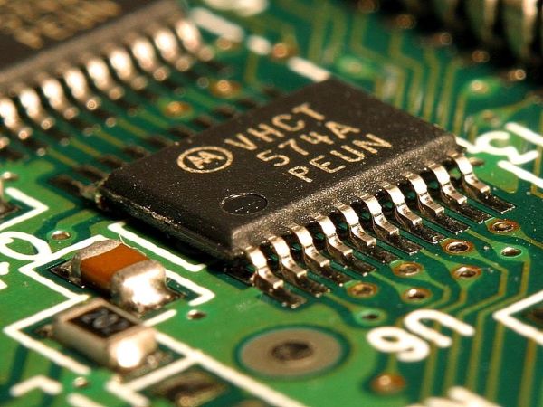
A close-up view of surface-mount components on a circuit board

Smaller Is Sometimes Better: Why Electronic Components Are So Tiny

Perhaps the second most famous law in electronics after Ohm’s law is Moore’s law: the number of transistors that can be made on an integrated circuit doubles every two years or so. Since the physical size of chips remains roughly the same, this implies that the individual transistors become smaller over time. We’ve come to expect new generations of chips with a smaller feature size to come along at a regular pace, but what exactly is the point of making things smaller? And does smaller always mean better?

Smaller Size Means Better Performance

Over the past century, electronic engineering has improved massively. In the 1920s, a state-of-the-art AM radio contained several vacuum tubes, a few enormous inductors, capacitors and resistors, several dozen meters of wire to act as an antenna, and a big bank of batteries to power the whole thing. Today, you can listen to a dozen music streaming services on a device that fits in your pocket and can do a gazillion more things. But miniaturization is not just done for ease of carrying: it is absolutely necessary to achieve the performance we’ve come to expect of our devices today. Continue reading “Smaller Is Sometimes Better: Why Electronic Components Are So Tiny”

Op Amps Before Transistors: A 600V Vacuum Tube Monster

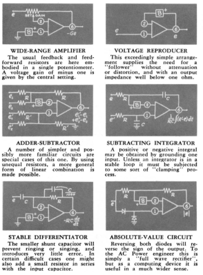
Op amps. Often the first thing that many learn about when beginning the journey into analog electronics, they’re used in countless ways in an overwhelmingly large array of circuits. When we think about op amps, images of DIPs and SOICs spring to mind, with an incredibly tiny price tag to boot. We take their abundance and convenience for granted nowadays, but they weren’t always so easy to come by.

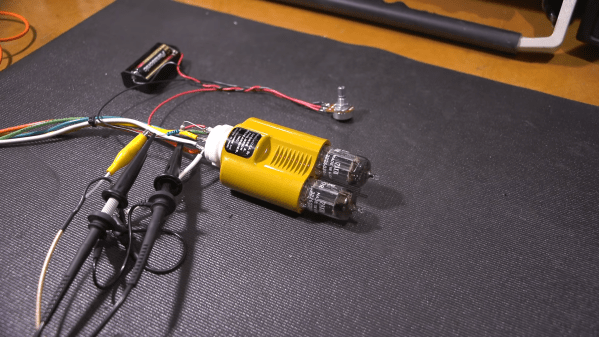
[Mr Carlson] serves up another vintage offering, this time in the form of a tube op amp. The K2-W model he acquired enjoyed popularity when it was released as one of the first modular general purpose amplifiers, due to its ‘compact form’ and ‘low price’. It also came with large application manuals which helped it to gain users.

In order to power up the op amp and check its functionality, +300V and -300V supplies are needed. [Mr Carlson] is able to cobble something together, since it’s very apparent that he has an enviable stash of gear lying around. A 600V rail to rail supply is not something to be taken lightly, though it does give this particular model the ability to output 100V pk-pk without any distortion.

The op amp is set up as an inverting amplifier, and once powered on proves to work flawlessly. As always, the video is an entertaining watch, stuffed full of retro electronics trivia. We’re big fans of [Mr Carlson]’s work, and have previously written about his adventures with a colossal walk-in AM radio transmitter, as well as his restoration of a 1930s oscilloscope and subsequent transformer de-potting.

Continue reading “Op Amps Before Transistors: A 600V Vacuum Tube Monster”

Biasing That Transistor: The Common Base Amplifier

We’ve previously remarked upon a generation lucky enough to be well-versed in microcontrollers and computersised electronics through being brought up on the Arduino or the Raspberry Pi but unlucky enough to have missed out on basic electronics such as how to bias a transistor, and to address that gap we’ve taken a look at the basics of transistor biasing.

All the circuits we worked with in the previous article had the transistor’s emitter taken to ground, took their input from the base, and their output from the collector. This configuration, called a Common Emitter amplifier is probably the most common, but it is far from the only way to use a transistor. Once you have set up the bias voltage as we described to the point at which the transistor is in its linear region, there are several other ways in which the device can be used as an amplifier. The subject of this article is one of these configurations, so described because it takes the transistor’s base to the ground instead of the emitter, as a Common Base amplifier. Continue reading “Biasing That Transistor: The Common Base Amplifier”

Won’t Somebody, Please, Think Of The Transistors!

At what age did you begin learning about electronics? What was the state of the art available to you at the time and what kinds of things were you building? For each reader these answers can be wildly different. Our technology advances so quickly that each successive generation has a profoundly different learning experience. This makes it really hard to figure out what basic knowledge today will be most useful tomorrow.

Go on, guess the diode!

Do you know the forward voltage drop of a diode? Of course you do. Somewhere just below 0.7 volts, give or take a few millivolts, of course given that it is a silicon diode. If you send current through a 1N4148, you can be pretty certain that the cathode voltage will be that figure below the anode, every time. You probably also have a working knowledge that a germanium diode or a Schottky diode will have a lower forward voltage, and you’ll know in turn that a bipolar transistor will begin to turn on when the voltage between its base and emitter achieves that value. If you know Ohm’s Law, you can now set up a biasing network and without too many problems construct a transistor amplifier.

Continue reading “Won’t Somebody, Please, Think Of The Transistors!”