1977 was a special year for computing history; this year saw the release of the 8085 following the release of the Z80 a year before. Three companies would launch their first true production computers in 1977: Apple released the Apple II, Commodore the PET 2001, and Tandy / Radio Shack the TRS-80 Model I. These were all incredibly limited machines, but at least one of them can still be used to browse Wikipedia.
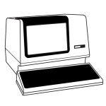
[Pete]’s TRSWiki is a Wikipedia client for the TRS-80 Model I that is able to look up millions of articles in only uppercase characters, and low resolution (128×48) graphics. It’s doing this over Ethernet with a very cool Model I System Expander (MISE) that brings the lowly Trash-80 into the modern era.
The MISE is capable of booting from CF cards, driving an SVGA display and connecting to 10/100 Ethernet. Connecting to the Internet over Ethernet is one thing, but requesting and loading a web page is another thing entirely. There’s not much chance of large images or gigantic walls of text fitting in the TRS-80’s RAM, so [Pete] is using a proxy server on an Amazon Web Services box. This proxy is written in Java, but the code running on the TRS-80 is written entirely in Z80 assembly; not bad for [Pete]’s first project in Z80 assembly.
 The Hackaday Retro Edition is our celebration of old computers doing something modern, in most cases loading the old, no CSS or Javascript version of our site.
If you have an old computer you’d like featured, just load up the retro site, snap some pictures, have them developed, and send them in.


I learnt Z80 Asm (or more accurately – machine code as I didn’t have an assembler) on a TRS80 Model I.
The memory issue here is more about making the code compatible with a wider range of hardware. 48kB will actually hold quite a bit of text. The old rule of thumb was 2kB to a ‘normal’ page so that would be about 20+ pages.
While on this topic (sort of), this computer has a monochrome res of 128px by 48px with no other graphics modes. I have a CPC6128 that has the modes: 640px/200px/monochrome, 320/200/4 color, 160/200/16 color.
I considered writing a renderer for the retro.hackaday.com site. The smallest image there is more than a screens resolution for most retro computers which isn’t a complete deal breaker in itself as images can be scaled. Images that scale well have strong contrasts and a limited range of colors and shades, pretty well the opposite of the horizon image on the page lol.
I visualised what that horizon image would look like reduced down to the res of a retro computer and decided that even ascii art would look better lol. At that point I decided against the idea.
Finally somebody did this! Not that I have a real machine to try it on, but I’ve been imagining how to write a program that would render HTML on a TRS-80. This one has a very clever solution here to the issue of hyperlinks with no mouse: assign a key to every link on screen.
In the link, he mentions he had problems with graphics aspect ratio. I don’t see why. The 128 x 48 graphics should have a ratio of exactly 1:2 width-to-height (because of the 4:3 ratio of old TVs).
In my own thought experiments, the sticking point was wondering how to connect ethernet to a TRS-80 with vintage or vintage-level hardware. Back in the 90’s dial-up internet era, RS-232, the 300-baud “Modem 1”, and a phone number could have gotten an all-stock hardware into the net. But now? Well yes, custom hardware like the MISE could solve all your problems! (My bright idea was serial thru the cassette port, since that’s the lowest common denominator to all Model I’s. RS-232 was only on the Expansion Interface, which was never reliable and are getting even more scarce on Ebay than Model I.)
I keep hoping somebody will design a vintage-hardware, real Z80 (no-microcontroller) Model 1 clone. Lots of true-Z80 CP/M boards with composite video out there now, but nothing Radio Shack compatible. If somebody reengineered the ZX81 with ULA, surely this an easier task! You’ll need to break open a keyboard to build it, however. The TRS-80’s keyboard was memory mapped: each key switch showed up as a bit in the memory space!
Correction: each pixel is 2:1, not 1:2. (You know what I meant!)
I had a poke around to see what’s on the web. The hardware would be easy to make (for what’s in the keyboard). 1 Z80, 1 Static RAM, 1 FLASH (ROM), 1 CPLD for everything else except keyboard.
I think the problem is copywrite on the ROM’s.
I would be happy to make a prototype if there are ROMS for it – perhaps the roms from a clone???
The Model 3 ROM can be freely used which is a good start. It’s not clear which company owns the rights to the M1 ROM. Maybe a flashable rom?
The M1 uses memory addresses for the keyboard and floppy I/O where the M3 uses more ports. It would be great if such a board was compatible with the original monitor (composite) and HDMI. And bus-compatible with perpherals as floppy, harddisk and printer (34 and 40 pin connectors).
I’m in to build one to get a defective M1 working again!!
Bart
Is there a schematic for the Model 3?
I would use FLASH anyway but that is not so useful unless you have a programmer.
Memory or ports for I/O doesn’t matter as long as the ROMs match.
Composite out is easy especially mono, HDMI is a different story and would be left for another day. HDMI is just not going to fit into the chip I was thinking for the rest of the logic.
Expansion can be done by exactly the same bus but I wasn’t going to do anything for expansion, just the keyboard bit. The expansion unit has an odd FDD controller chip that I am not familiar with and I am sure it would not be available today. In any case I would prefer an SD card to FDD so it would be a re-design from scratch. At that stage you could think about HDMI.
I had a quick look at the schematics for the M1 and LX80?? expansion. They were broken into pages so I didn’t follow them too well. The M1 keyboard would fit into 4 chips (CPU, RAM, FLASH, CPLD) and be cheap to make. So it’s down to the copywrite issues. I assume the M3 isn’t much more complex???
The expansion had two chips that I didn’t recognise. One was a FDC and the other – I have no clue. In any case both will be obsolete by now.
Do you have links to some decent schematics? I struggled to find anything.
I am on hackaday.io. better to chat there if we can. if you sign up – send your screen name.
I have these schematics. The FDC is indeed outdated and very hard to find, but since it’s part of the Expansion Interface it can be left alone. The connector should be able to connect to this EI if needed. Of course an SD Card would be more flexible. The tape interface can be skipped as well ;-)
I made an account with the screen name Bart.H or use twitter with my name on top of this comment.
Can’t find your profile on hackaday.io and I don’t have twitter.
Try Bart Hemstra
The Model 3 is an “all-in-one” unit with monitor, keyboard and drives all in one case. A “model 3” without monitor will be very weird, to say the least.
For more technical information about the Model 1, “The Custom TRS-80 and Other Mysteries” has a lot of detail. It talks about hardware modifications, but starts with explaining the base hardware first.
https://archive.org/details/Custom_TRS-80_and_Other_Mysteries_1982_Dennis_Bathory_Kitsz_a
Unlike the suggestion below, I would NOT drop certain things like the cassette interface. TRS-80 game players would be very unhappy–it was the only way it could output sound!
For ROM copyright, who knows? Level 2 (and up) Basic, which is 90% of the ROM, was absolutely Microsoft’s. (Most of which was still Bill Gates’s personally-written 8080 code.) The rest (I/O routines) was Radio Shack’s, going back to Level 1. Radio Shack did release the disk file containing the Model 3 ROM, since the Model 4 was RAM-only and needed it loaded for old programs. Radio Shack sold off ALL their homegrown computer stuff in the early 1990’s to AST. According to discussions on the comp.sys.tandy newsgroup, no one knows who legally owns it now.
It took me decades to realize how cool my dad was for buying a ‘computer’ in 1979. That big red led on the right side of the monitor takes me back. However, though we did have a game that produced sound called hustler and required no speaker or cassette.
The memory map of the Model I is quite simple:
0000H – 2FFFH is Level II Basic ROM
3000H – 37DDH is empty
3800H – 3880H is hardwired keyboard matrix
3C00H – 3FFFH is 1K video RAM
4000H – FFFFH is user RAM
JD is right, the cassette-port is certainly needed for sound! It is port FFH, the Model 3 uses more ports. A few non-used addresses are used for FDD and HD interfacing. The complete schematics and even commented ROM-listings are available. I have a defective Model I which I would like to turn in a working machine. Using emulation (I have it running on a Raspberry PI) is one possibility, your idea is an even better way of getting it to work. Alas I don’t have much knowledge of a CPLD.
I emulated a model I a while ago on a PIC32 .
https://www.youtube.com/watch?v=9goHfRxkx5w
I have started a project for this here –
https://hackaday.io/project/5565-trs-80-compatible-replica
Add your requests / comments or request membership if you have a hackaday.io profile.